Table of Contents
Advertisement
Quick Links
Advertisement
Table of Contents

Related Manuals for AVer VC550


Summary of Contents for AVer VC550
- Page 1 VC550 User Manual...
- Page 2 Federal Communications Commission Statement NOTE: This equipment has been tested and found to comply with the limits for a Class A digital device, pursuant to part 15 of the FCC Rules. These limits are designed to provide reasonable protection against harmful interference when the equipment is operated in a commercial environment. This equipment generates, uses, and can radiate radiofrequency energy and, if not installed and used in accordance with the instruction manual, may cause harmful interference to radio communications.
- Page 3 © 2022 AVer Information Inc. All rights reserved. | April 29, 2022 All rights of this object belong to AVer Information Inc. Reproduced or transmitted in any form or by any means without the prior written permission of AVer Information Inc. is prohibited. All information or specifications are subject to change without prior notice.
- Page 4 WARNING To reduce risk of fire or electric shock, do not expose this appliance to rain or moisture. Warranty will be void if any unauthorized modifications are done to the product. Do not drop the camera or subject it to physical shock. ...
- Page 5 Tel: +81 (0) 3 5989 0290 テクニカル・サポート: VCInfo.JP@aver.com Vietnam Branch Office Công ty TNHH AVer Information (Việt Nam) Tầng 5, 596 Nguyễn Đình Chiểu, P.3, Quận 3, Thành phố Hồ Chí Minh 700000, Việt Nam Tel: +84 (0)28 22 539 211...
-
Page 6: Table Of Contents
Contents Package Contents ................1 Product Introduction ................. 3 Overview ..................3 Camera LED Indicator ............... 4 Speakerphone .................. 4 Speakerphone button ............... 5 Speakerphone LED Indicator ............5 Installation ..................6 Camera .................... 6 Speakerphone .................. 8 Remote Control ................9 Pan and Tilt Angle .............. - Page 7 Ceiling Mount Installation (Optional) ........28 Secure the Cables ..............32 Operating the Camera ..............33 Make a Video Call ..............33 Make a Connection through the Browser ........34 Web Settings ................37 First Time Login ............... 37 Live Screen Operation ............. 38 Set Up the Preset ..............
- Page 8 Camera Binding ..............47 HDMI Screen Layout ..............48 Noise Reduction ..............49 Brightness ................50 Saturation ................50 RS232 Settings ..............51 Video Format Settings ............. 52 H.264 Profile ..............52 IP Stream Resolution only ..........52 Frame Rate ................ 53 Bit Rate ................
- Page 9 Time Correction Mode ............61 Information ................. 62 PTZApp 2 ..................63 Install PTZApp 2 ..............63 Use PTZApp 2 with USB Devices ..........63 Use PTZApp 2 with a Virtual Stream ........72 EZLive .................... 74 Use AVer EZLive ..............74...
-
Page 10: Package Contents
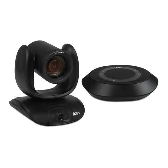
Package Contents USB 3.1 Type-B Mini DIN9 to Mini Remote Power Adapter Camera Unit to Type-A Cable DIN8 RS232 Control & Power Cord* (3m) Adapter Cable HDMI Cable Wall Mount Drilling QR Code Screws for Mount (3m) Kit** Paper Card 46.00[1.81] Ø... - Page 11 (165 x 165 x 612 mm)( *Optional Accessories will vary depending on the country where it is sold. **This is a dual lens camera and doesn’t support upside down installation. To mount on ceiling, please purchase ceiling mount from AVer.
-
Page 12: Product Introduction
Product Introduction Overview 5 6 7 8 9 10 Optical Zoom Lens HDMI Port** IR Sensor USB 3.1 Type B Port AI Lens* RS232 In/Out Port Status LED PoE Port*** Kensington Lock DC 12V Power Jack * AI Lens: Users can see AI lens preview image in PTZApp 2, IP web page or HDMI out to check camera installation location. -
Page 13: Camera Led Indicator
Camera LED Indicator Solid blue: Power on Solid red: Start-up Solid orange: Only power cable connected Solid blue: Video on Solid white: USB cable is connected but camera doesn’t have any streaming out Gesture control Blue light blinks for 2 seconds: Successfully wake up gesture control function by any valid gesture command. -
Page 14: Speakerphone Button
Speakerphone button Bluetooth Volume Up Blinking Blue: Activation and connection state Solid Blue: Connection successful Mute Un-mute Phone In Volume Down Solid Blue: Connect with external device Off: No device connected Answer Call End Call Speakerphone LED Indicator Button LED Indicator Status White light Adjust the volume up and down. -
Page 15: Installation
Installation Camera Connect the camera to power outlet. Connect the necessary cables. [Notes] Secure the USB and RS232 cables with attached screws. Make sure the cable is well connected to the connector on the camera before securing the cable. - Page 16 Connect the camera to the computer/laptop. [Notes] Use the USB 3.1 cable included in the package. CAM550 has the USB 3.1 port which is USB 2.0 compatible. Maximum resolution/fps for USB 2.0 and USB 3.1 port are shown below. USB 2.0 USB 3.1 HDMI...
-
Page 17: Speakerphone
Speakerphone 1. Connect the speakerphone to a power outlet. 2. Connect the speakerphone to the laptop/PC. [Note] Use the USB cable that is included in the package. Remove the back cover for cable installation. Or, enable the Bluetooth function on the laptop/PC to make a wireless connection. Laptop [Note] ... -
Page 18: Remote Control
[Note] The default is Off. If you don’t do any binding, no matter you press camera 1 or 2, 3 button on the remote control, you can control all the AVer USB cameras around you. 2. Camera Directional Use the directional buttons on the... - Page 19 want to see the icon display, please go to PTZApp 2, find “On Screen Menu” function and select “Off”. [Notes] Default is Manual Framing. SmartFrame deploys face and body detection technology. People wearing masks and side facial profiles can still be detected. The maximum detection distance is 7~10 meters away from the camera.
- Page 20 To Save a Preset – Move camera to desired position. Press and hold the preset button until you receive the save message on the screen. Select preset position button 0-9 to store the current camera position. Repeat steps if needed. To Load a Preset - Press the preset button and preset position button 0-9 to load a saved camera position.
- Page 21 “ ” for 1 second to force camera to enter sleep mode. This will end any video streaming. To wake up the camera, press the button or any directional button for 1 second. This mode is not functional while USB streaming is on. 8.
-
Page 22: Pan And Tilt Angle
Pan and Tilt Angle... -
Page 23: Installation
Installation Device Connection Use USB cable to connect the CAM550 to your PC/laptop (refer to diagram above). Connect the power to the CAM550; power indicator will light up and camera head will rotate. Install PTZApp 2 on laptop or PC that is connected with CAM550. The app can be used to adjust and setup the parameters of the camera (refer to the section of PTZApp 2). - Page 24 [Notes] Use the USB 3.1 cable included in the package. CAM550 has the USB 3.1 port which is USB 2.0 compatible. Maximum resolution/fps for USB 2.0 and USB 3.1 port are shown below. USB 2.0 USB 3.1 HDMI M-JPEG M-JPEG - 640x480 or less...
-
Page 25: Power Connection
Power Connection The power supply can be plugged into the wall outlet or drawn from PoE switch (Ethernet). Wall outlet [Note] To ensure stability of IP video streaming, please use CAT 5e FTP cable (not included). -
Page 26: Hdmi Connection
HDMI Connection Connect with TV or monitor through the HDMI port to display camera video on the screen. Hold button for 1 second on remote control to call out the screen layout option. Select the camera image layout firstly. The default is PIP1, showing optical zoom lens image as main screen and AI lens image as small view. - Page 27 Lens 1 The PTZ camera focuses on speaker Lens 2 Shows all participants After choosing the image layout, short press the OSD menu button and then the setting page will show up. Press right direction button to enter and configure the parameters of the camera. Short press the OSD button twice or hold it for 1 sec.
-
Page 28: Rs232 Connection
RS232 Connection Camera RS232 Port Pin Definition Mini DIN9 Function I/O Type Signal Description PIN # Output Data Terminal Ready Input Data Set Ready VISCA IN Output Transmit Data Input Receiver Data Output Data Terminal Ready Input Data Set Ready VISCA OUT Output Transmit Data... - Page 29 Computer/Keyboard Controller and Camera Connection Direct Connection If users do not use AVer RS232 adapter cable, please refer to the pin connection shown below. Mini DIN9 to DB9 Cable Camera controller Camera Camera controller or PC (Mini DIN9) (DB9) 1. DTR (IN) 1.
- Page 30 Use the supplied RS232 mini DIN9 to mini DIN8 cable RS232 mini DIN9 to mini DIN8 cable** VISCA in (Female) Mini DIN8 to DB9 cable* VISCA out (Female) Camera controller Camera controller or PC Camera (DB9) (Mini DIN8) 1. DCD 1.
- Page 31 * Mini DIN8 to D-Sub9 (DB9) cable 064AOTHERBPK is an optional item. ** RS232 mini DIN9 to mini DIN8 Cable Pin Definition Mini DIN9 Connect to AVer camera Mini DIN8 (IN) Connect to next camera Connect to camera controller or PC...
- Page 32 Camera Cascade Connection Direct Connection If users do not use AVer RS232 adapter cable, please refer to the pin connection shown below for cascading cameras. Total can connect up to 7 cameras. Camera 1 Camera 2 (Mini DIN9) (Mini DIN9) 1.
- Page 33 Connect camera with AVer mini DIN9 to mini DIN8 adapter cable. Connect the mini DIN8 female side to male mini DIN8 Visca cable (Users have to buy it in the market) and then connect AVer mini DIN9 to mini DIN8 adapter cable again to connect to next camera.
-
Page 34: Wall Mount Installation
Wall Mount Installation 1. Use the drilling paper included in the package to drill the holes in the wall where the user wants to mount the camera. 46.00[1.81] Ø 5.50[Ø 0.22] 51.00[2.01] P/N: 303AU340-AGR 2. Use the screws (not included) to secure the L-mount bracket on the wall. - Page 35 3. Then, assemble the L-mount brackets with screws (included in package). Screw size: M4 x8mm (x2) 4. After assembling the L-mount brackets, use the screws (not included) to secure the lower part of L-mount brackets on the wall. Screw For Cement wall: M4 x20mm self-tapping screws (x2) + Plastic conical anchor For Wooden wall: M4 x20mm self-tapping screws (x2)
- Page 36 5. Pass the cables through the hole on the L-mount bracket and connect the cables to corresponding connection ports. 6. Use the remaining screws (included in package) to secure the camera on the L-mount bracket. 1/4”-20 L=7.5mm (x2) Screw:...
-
Page 37: Ceiling Mount Installation (Optional)
Ceiling Mount Installation (Optional) You can use the optional ceiling mount accessories to mount the camera to the ceiling. Package Content Mount bracket x 1 Camera bracket x 1 Back cover x 1 Screw (M4*8) x 8 Washer x 8 (165 x 165 x 612 (170 x 260 x 194 (54 x 22 x 525... - Page 38 To mount the camera to the ceiling: 1. Drill the hole on the ceiling. Use screw to secure the mount bracket on the ceiling. Screw: 4 M6 x 50mm (Not included in package) 2. Use the supplied screws with washers to secure the camera bracket to the mount bracket.
- Page 39 To mount the camera to the calcium silicate ceiling: 1. Please purchase support bracket for supporting camera mount bracket on calcium silicate ceiling. Then, secure the support bracket on the light steel frame structure. 2. Drill the hole on the calcium silicate ceiling. Open a hole on the calcium silicate ceiling to allow camera cables to pass through.
- Page 40 7. Next, secure the back cover with screws and washer. Screw: 4 M8 x 4 + 4 Washer Completed.
-
Page 41: Secure The Cables
Secure the Cables The USB and RS232 cables have a screw on the cable for securing cable on the camera. Install the cable first and tighten the screw to secure the cable. [Note] Make sure the cable is well connected to the connector on the camera before securing the cable. -
Page 42: Operating The Camera
Operating the Camera Make a Video Call A computer is required to use this device. Make sure all devices (CAM550, laptop/PC, TV/monitor) are well connected and powered on. ® Run your video application (Zoom, Microsoft Teams, Skype for Business, Skype, Google Meet, ®... -
Page 43: Make A Connection Through The Browser
Make a Connection through the Browser CAM550 has an Ethernet port for IP streaming and allows administrators to remotely control and set up the camera via an internet access. Moreover, CAM550 also supports RTSP and RTMP functions. For more details, please contact our technical support. Make sure the CAM550 has an internet access connection. - Page 44 Click weblink icon ( to launch Chrome page. Please enter the password (default password is aver4321). User will be asked to set a new account and password. (Please enter PTZApp 2 to reset password back to default while password is forgotten.) After editing IP address, user can access web settings of the camera with only Ethernet cable connection.
- Page 45 ** To support IP address changes in groups, user can download AVer IP Finder app. 1. Download the IP Finder from https://www.aver.com/download-center (Global), https://www.avereurope.com/download-center (Europe), or https://www.averusa.com/business/support (USA). 2. Run the IP Finder. 3. Click “Search”, and all available devices will be listed on the screen.
-
Page 46: Web Settings
Web Settings CAM550 supports Ethernet connection; users can enter the IP address into the web browser to connect to the camera for detail settings. First Time Login To find the IP address of the camera, please refer to “Make a connection through the Browser” section. -
Page 47: Live Screen Operation
Live Screen Operation User can control the camera direction, zoom in/out, and preset selection. [Notes] The system will force the previous login to log out, when there is a second login. If the web page is idle without any request for more than 4 hours, user will be logged out. ... -
Page 48: Set Up The Preset
Set Up the Preset User can set 10 preset positions. In live screen, use ▲ , ▼ , , and zoom in/out buttons to adjust the camera screen view to desired position. Select “Set” button and click on the preset number to save the preset. The system will capture the preset screen view and display in preset number frame. - Page 49 After setting up the preset positions, you can start performing the function. Select the “Load” button and then click on the preset numbers, the live screen will move to the preset screen view.
-
Page 50: Camera Settings
Camera Settings The video icon is to turn on camera live view while adjusting any settings. Click the icon to Click the icon to show/hide hide people count people count number & and the time stream interval. interval of enabling IP icon shows the live streaming the IP address of... -
Page 51: Tracking Mode
Tracking Mode Select Setting > Camera > Tracking Mode > Off, Manual Frame, Auto Frame, or Preset Framing. Off: Tracking mode is disabled. Manual Frame: User one-click SmartFrame button and camera will adjust view angle to fit all participants in screen. - Page 52 shoot the preset zones instead of focusing and zooming into presenter. PTZ Camera tracks and frames all the participants if none of them touch any preset area. To keep the screen stable, whenever there is a person in the area, the camera won’t move any more until no one shows up. However, the camera can detect the direction where the last person goes.
-
Page 53: Ai Detection Source
AI Detection Source Select Setting > Camera > AI Detection Source. Secondary Lens: When selecting AI detection source in secondary lens, people have to be within its field of view to trigger framing detection. PTZ Lens: 1. When selecting AI detection source in PTZ lens, people have to be within its field of view to trigger framing detection. -
Page 54: Gesture Control
Tight: It provides a close-up view of meeting participants. Medium: It provides a medium view of meeting participants. Wide: It provides a wide view of meeting participants. Gesture Control Enable gesture control allows user to use hand to control camera for turning on/off tracking function, zooming in/out. - Page 55 Zoom In You have to be within the view of AI lens. Raise your hand over your head for 2~ 3 second to zoom in camera. If there are more than one people raising the hand, the camera will follow the 1st one until he puts down the hand.
-
Page 56: Sleep Position
With multiple cameras connection, users can set each camera to buttons 1 to 3 on the remote control. Select Setting > Camera > Camera Binding > Camera1, Camera2, or Camera3. [Note] When camera binding is off, press camera 1, 2, or 3 button on the remote control can control all the AVer USB camera nearby you. -
Page 57: Hdmi Screen Layout
Save Preset Enable/disable “save preset” function. When applicable, IT personnel can limit end-user access to change preset points by locking “save preset” function and switching this function off. When off, user can’t save preset points via IR remote, Hot key, VISCA, and webpage. Select Setting >... -
Page 58: Noise Reduction
Image Settings Frequency Select the frequency of the camera. Select Setting > Image > Frequency > 50 HZ or 60 HZ. Main Lens 1/AI Lens 2 Select Main Lens 1 or AI Lens 2 to setup lens’ parameters – White Balance, Noise Reduction, Brightness, Sharpness, and Saturation. -
Page 59: Brightness
Brightness Adjust the value of brightness. Select Setting > Image > Brightness > 1 ~ 9. Sharpness Adjust the value of sharpness. Select Setting > Image > Sharpness > Off, Low, Middle, or High. Saturation Adjust the value of saturation. Select Setting >... -
Page 60: Rs232 Settings
Enlarge Total Zoom Up To 24x Enable/Disable enlarge zoom up to 24x. The default is 18x. RS232 Settings When CAM550 connects with PTZ camera controller through the RS232 port, please setup ADDR, Baud Rate, Protocol, and Visca Over IP settings. Select Setting >... -
Page 61: Video Format Settings
Video Format Settings H.264 Profile While in live broadcasting, user can choose preferable profile to get best streaming quality. Select Video Format > H.264 Profile > Baseline Profile or High Profile. IP Stream Resolution only Set up the resolution for IP stream. Not supported for USB video stream. Select Video Format >... -
Page 62: Frame Rate
Frame Rate Set up the frame rate value. Select Video Format > Frame Rate > 60 FPS, 30 FPS, or 15 FPS. Bit Rate Set up the bit rate value. Select Video Format > Bit Rate > Auto, 512 Kbps, 1 Mbps, 2 Mbps, 4 Mbps, 8 Mbps, 16 Mbps, or 32 Mbps. -
Page 63: Rtmp
RTMP Set up for uploading the camera’s live view to the broadcasting platform (e.g. YouTube). Select Video Format > RTMP. 1. Locate the RTMP server URL and stream key from the broadcasting platform and enter in Server URL and Stream Key fields. 2. -
Page 64: Network Settings
Network Settings DHCP Enable DHCP function. Select Network > DHCP. A message is shown and clicks Continue to confirm. Static IP Assign a fixed IP address to the camera. 1. Select Network > Static. 2. Click pencil icon and enter the IP Address, Gateway, NetMask, and DNS in the corresponding fields. -
Page 66: System Settings
Update the camera’s firmware. Select System > FW Update > Auto Update or Manual Update. Auto Update: The system will check firmware version from AVer server and request to update. Manual Update: To update the firmware from specific location. -
Page 67: Factory Default
Factory Default Reset the camera back to factory default setting. 1. Select System > Factory Default > Reset. 2. User can choose to keep current IP address/Web access password or back to default. 3. Select Continue to reset back to factory default. [Note] When factory default is activated, the password of Webpage login will not be set to default. -
Page 68: Change Password
Change Password Change the web login password. The default password is “aver4321”. 1. Select System > Change Password > Change WEB Access Password. 2. Enter the old account and password. Select Continue. 3. Enter the new account and password. Select Continue to save the new setting. 4. -
Page 69: Ssl Certificate
SSL Certificate Import the SSL certificate from specific location. 1. Select System > SSL Certificate > Import. 2. Select the type by clicking “+”. 3. Direct the file location. 4. Select Import. [Note] If you want to disable SSL certificate function, please use PTZApp 2 to switch off this function. Date Format Select the date format. -
Page 70: Time Correction Mode
Time Correction Mode Adjust time automatically or manually. Select System > Time Correction Mode > Auto or Manual. Auto: The system time will be set by NTP server on the network. Click the pencil icon of NTP Server and enter the URL of NTP server. Select the Time Zone. Select NTP Update to save setting. -
Page 71: Information
Information Display the information of Model Name, Firmware Version, Serial Number, IP Address, and MAC Address. Select System > Information. -
Page 72: Ptzapp 2
AI tracking functions and some advanced image settings, pan, tilt, and zoom the camera. Install PTZApp 2 Please go to https://www.aver.com/download-center (Global & European Headquarters) or https://www.averusa.com/business/support/ (USA) to download the PTZApp 2. After downloading, double-click on the file and follow the on-screen instructions to complete the installation. - Page 73 Choose “USB device” and connect CAM550 to PC/laptop with USB cable When the camera is detected, the product card will show up. Set up IP address. The camera default IP address is 192.168.1.168. Click pencil icon ( ) to edit IP address. Click the setting icon to change Language, Hotkey Control, and PTZApp 2 Version.
- Page 74 Language: Select desired language and click the check icon to confirm the selection. Hotkey Control: User can control the camera by using keyboard. This is a general list for all AVer USB Cameras. Backlight control equals to WDR function in CAM550.
- Page 75 Usage Data: Should you click the check mark, PTZApp2 will automatically send us the diagnostic and usage data to help us improve PTZApp2. The collected data is anonymous and cannot identify users. EZManager Pair: Enter THE 4-Code ID and IP to connect to EZManager.
- Page 76 Information: Click the drop-down triangle icon to review the information of camera. To minimize the information, click the triangle or the bottom area of the information icon. Camera: Click the camera icon to view the camera live view. IP address is displayed as well. Click the X icon to close the camera live view.
- Page 77 Full Screen: PTZApp 2 can switch to full screen mode. Click “ ” icon and video screen will switch to full screen mode. In full screen mode, user can use direction panel to control camera direction. Click “ ” icon to go back to normal screen view. The resolution of full screen mode is 1080p/ 30fps.
- Page 78 People Count and Stream Interval: Click the icon to show people count number and stream interval. Click the icon to hide the stream interval. Control Panel: To control the camera direction, zoom in and out during your video call.
- Page 79 Setting: Click “Setting” button to set up parameters of the camera and speakerphone. Click arrow icon to leave the Setting page. PTZ Control: Use control panel to set up preset positions. Since most of operations are the same as web page, refer to Set Up the Preset section (pages 39) for detailed setup.
- Page 80 10. PTZApp 2 Quit & Restore: To quit the application, right-click the icon on the system tray and select “Quit”. If you can’t launch PTZApp 2 right after installation, please right –click the icon and choose “Restore”.
-
Page 81: Use Ptzapp 2 With A Virtual Stream
Use PTZApp 2 with a Virtual Stream With this function, you can have a virtual meeting with only Ethernet connection and get rid of USB cable connection. Make sure the camera is connected with Ethernet and under the same subnetwork as the meeting room PC (e.g. - Page 82 Virtual Stream technology uses an RTSP stream. If you set a password for RTSP, you will be asked to provide that password while enabling this function. Launch VC software (e.g. Zoom, Teams, Skype) and choose AVer USB VCam as the video source to start collaborating.
-
Page 83: Ezlive
EZLive Please go to http://www.aver.com/download-center to download the AVer EZLive software. After downloading, double-click on the file and follow the on-screen instructions to complete the installation. Use AVer EZLive During a video call, EZLive can help user to do: (1) Camera ePTZ (2) Volume control for the speaker connected (3) Capture camera’s still images...