Advertisement
Quick Links
Advertisement

Related Manuals for Absen X-Box


Summary of Contents for Absen X-Box
- Page 1 X-Box User manual - 1 -...
- Page 2 - 2 -...
-
Page 3: Safety Information
Follow safety instructions in this manual and on the product. If you have any questions, please seek help from Absen. Beware of Electric Shock! • To prevent electric shock the device must be properly grounded during installation, Do not ignore using the grounding plug, or else there is a risk of electric shock. - Page 4 case of any failure the power can be promptly disconnected. • Before using this product check all electrical distribution equipment, cables and all connected devices, and make sure all meet current requirements. • Use appropriate power cords. Please select the appropriate power cord according to the required power and current capacity, and ensure the power cord is not damaged, aged or wet.
- Page 5 Product Disposal • Any component that has a recycling bin label can be recycled. • For more information on collecting, reusing and recycling, please contact the local or regional waste management unit. • Please contact us directly for detailed environmental performance information.
- Page 6 X-Box 1.1 The interface of Device HDMI IN SPDF HDMI OUT AUDIO OUT RS-232 4 / 5 USB2.0 POWER - 6 -...
-
Page 7: Standard Packaging
1.2 Standard Packaging 1.2.1 Standard packaging of X-Box ⚫ The standard packaging of X108 is carton packing which can support for 10kg without any deformation ⚫ The first layer carton packaging size: :1360x268.5x34.5mm ⚫ The second layer carton packaging size:1360x268.5x34.5mm ⚫... -
Page 8: Product Installation
Second layer First layer 2. Product Installation The product can realize installation of wall mounting ,mobile stand and Electric lifting bracket. 2.1 Installation tools serial serial Tool name photos Tool name photos number number - 8 -... - Page 9 art knife Pre-maintenance tools PH2 Phillips Allen key screwdriver flexible rubber mallet sleeve laser level pneumatic drill 2.2 Wall Mount Installation Guide 2.2.1 Installation step of wall mounting equipment Step 1: Taking out the back frames from packaging, including the horizontal and vertical beams. Setting it up on the ground with the front side facing up (the side with the silkscreen logo on the beams is the front side);...
- Page 10 Note: When installing the wall bracket, the groove at the bottom of the wall bracket needs to be in contact with the protruding part of the corner code. Step 3: Using 8pcs M6X20 to lock the safety screws at the angle code to make sure the wall bracket will not mover, after finish the installation of the wall bracket.
- Page 11 Step 2: Install the box columns in the order of 2-3-1-4, with the hook connectors on the back of the box hooked into the grooves of the back frame beam profile. Move the box so that it is centered and aligned with the marking line on the crossbeam, and install the box safety screws using two M4X10 screws (as shown in Figs.
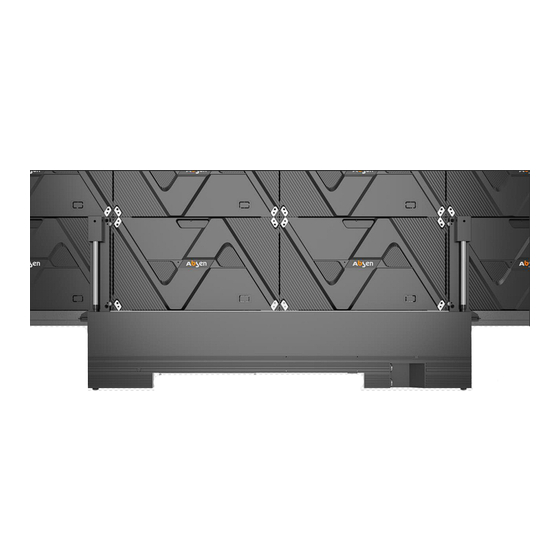
- Page 12 2.2.3 Trims and control box installation Step 1: Control Box Installation: Lift the control box upward from the back of the box to install it between the first and fourth columns, and then use 4 M6*30 screws to lock it from the front to complete the installation of the control box structure.
- Page 13 2.2.4 Connect the power and network cables Step 1:Connect the power cord and network cable Connect the power cord and the network cable, from the left side of the lower edge of the holes through the 4 main power cord, according to the power cord labeling order from left to right as the first column to the fourth column order, connect the power cord and connect the ground wire at the bottom of the box;...
- Page 14 2.2.5 Install the bottom trim cover and connect the screen on button 5P cable Power On Button 5Pin Cable USB subversion 2.2.6 Mounting modules Because this product adopts the whole screen calibration, in order to ensure the best display effect, it must be installed in accordance with the order of our company's identification as the figure shown on below.
- Page 15 Numbering instructions: The first bit is the screen number; the second bit is the box row number, from top to bottom, the top is the first row; the third bit is the box column number: The fourth bit is the module number For example, 1-1-1-2 is the second module of the first row and column of the first screen.
- Page 16 2.3.1The steps of installation for mobile stand Step 1: Taking out the mobile brackets from packaging and using 12 M6X16 screws to assemble the crossbeam and mobile bracket legs (Note: the crossbeam has an arrow to indicate the arrow upward, and the herringbone leg has a step at the front) 2.3.2 Screen installation Step 1:Taking out the box and usinguse 20 M6X16 screws to install the hook connection piece on the back of the...
- Page 17 Figure 1 Figure 2 Step 3: Using 30 M8X20 fixing screws to install the box within the leveling connection piece (as shown in Figure 1), use 4 M5X40 screws to install the box security screws, to ensure that the screen will not move from side to side (as shown in Figure 2 Note: Fixed corners can be) Figure 2 4 x M5X40 screws...
- Page 18 4 x M6X30 Front mounted control box Rear mounting: use four M6X16 screws to fix the control box from the back (mobile version is recommended to fix the control box from the back for easy installation) 4 x M6X16 screws Rear mounted control box Step 2 (Non-touch version,the touch version content in part 2.4 ): The installation of top, left and right trims: The upper, left and right trims are fixed and mounted through the trims...
- Page 19 Using 6 M6X16 countersunk head screws to install the bottom trims on the bottom side of the cabinet, and using 4 KM3X8 screws to fix the bottom trims with the connecting piece, which can use for adjusting the flatness . Attach the wrap-around connector piece using 4 KM3X8 screws.
- Page 20 Step 2: Getting through 4 main network cables from the hole of right side of bottom trim. The order of cabinets is the same as above from left to right as the first column to forth column, which will be corresponding with the order of label on network cables Then, connecting the network cables.
- Page 21 2.3.5 Install the bottom trim cover and connect the screen on button 5P cable USB subversion Power On Button 5Pin Cable 2.3.6 Mounting Modules Because this product adopts the whole screen calibration, in order to ensure the best display effect, it must be installed in accordance with the order of our company's identification as the figure shown on below.
- Page 22 Numbering instructions: The first bit is the screen number; the second bit is the box row number, from top to bottom, the top is the first row; the third bit is the box column number: The fourth bit is the module number For example, 1-1-1-2 is the second module of the first row and column of the first screen.
- Page 23 2.4 Trim installation (touch version) 2.4.1 list of touch version trim 2.4.2 Schematic diagram of Trim for touch version Corner outer cover (upper left) ABS-4X4-3/4-B ABS-4X4-3/4-B ABS-4X4-3-A ABS-4X4-4-A ABS-4X4-6-A ABS-4X4-1-A ABS-4X4-1/6-B ABS-4X4-1/6-B...
- Page 24 2.4.3 Steps of installation Step 1: Installing the top , left and right trims which the last letter is “ A “. The installation method can be read in part 2.2.2 PM3X8 screw to connect the bottom trim. Step 2: Using two Attach the bottom trim to the lower side of the cabinet by five M6X16 countersunk head screws.
- Page 25 Pay attention to the position of the pins when inserting them. ⚫ Avoid bending pins due to hard mounting ⚫ Take care of alignment when plugging in the wires; ⚫ Step 5: The process of connecting power cords and network cables is same as non-touch version. (In part 2.2.4 or 2.3.4) Step 6: Using three HM3X6 screws to fix the secure ground wire (lower left, upper left, lower right).
- Page 26 Step2: Touch Frame connects to PC by USB Test result: Pass Test Result: NG The matrix can be viewed by clicking on it...
- Page 27 2.4.5 Connecting to PC to test drawing The diameter of the touching object used to draw the line test (a stylus is recommended) needs to be greater than ➢ 8mm; When drawing a line with more than two points, the gap between two touches (two pens) is required to be more than ➢...
- Page 28 3.Guide of maintenance 3.1 maintenance tools Tools Picture Function Front maintenance Install/Remove LED tool Module Maintenance tool PH2 Phillips Remove/install the screws list for the HUB, receiving card screwdriver and power supply Measuring power supply Multimeter system 3.2 Instruction of maintenance 3.2.1 maintenance of modules The modules of X108 can be quickly removed by passive front maintenance.
- Page 29 3.2.2 HUB/Receiving card /Power maintenance Using the maintenance tool to remove the module which is the faulty panel, and then using a screwdriver to remove the screw fixing the HUB board for replacement HUB board maintenance Picture ❶ After removing the module with the maintenance tool, remove...
- Page 30 1. When touching LED light boards or panels, paying attention to anti-static and do the following effective protection: a. Wear a grounded electrostatic wrist strap or electrostatic gloves; b. The screen is strictly grounded, and the grounding resistance is required to be ≤10 ohms, and a point inspection is carried out every six months;...
- Page 31 Damage to the equipment caused by failure to follow documentation is not covered by the equipment warranty. Professional Service, Best Experience Absen has built up a global network , able to provide prompt and professional local services. Absen service philosophy Initiative...
Need help?
Do you have a question about the X-Box and is the answer not in the manual?
Questions and answers