Sign In
Upload
Download
Table of Contents
Contents
Add to my manuals
Delete from my manuals
Share
URL of this page:
HTML Link:
Bookmark this page
Add
Manual will be automatically added to "My Manuals"
Print this page
×
Bookmark added
×
Added to my manuals
Manuals
Brands
Absen Manuals
Monitor
X3
User manual
Absen X3 User Manual
Hide thumbs
1
Table Of Contents
2
3
4
5
6
7
8
9
10
11
12
13
14
15
16
17
18
page
of
18
Go
/
18
Contents
Table of Contents
Bookmarks
Advertisement
Table of Contents
1
Table of Contents
1
Safety Information
2
Product Introduction
2.1
About X3/X5/X7
2.2
Product Dimensions
2.3
Product Specifications
2.4
Product Value Features
3
Product Components
4
Product Assembly
5
Cabinet Installation and Dissassembly
5.1
Rigging Bar Installation
5.2
Cabinet Mounting
6
Product Wiring
6.1
Power Cord Cabling Instructions
Download this manual
LeadingLEDApplications
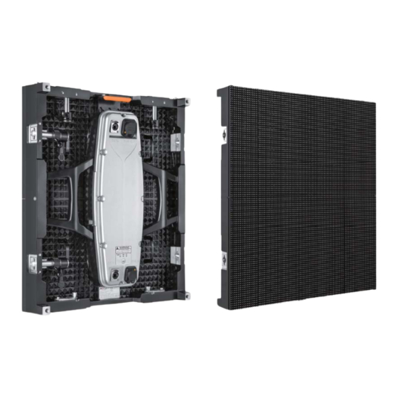
X3/X5/X7
User Manual
OUTDOOR & INDOOR
YOUR CHOICE
R
Patented Product
FCC
ETL
TUV-CE
High Refresh
Back-up
High Brightness
Front Servicing
Easy Installation
High IP Rating
Rate
Power Supply
Table of
Contents
Previous
Page
Next
Page
1
2
3
4
5
Advertisement
Table of Contents
Need help?
Do you have a question about the X3 and is the answer not in the manual?
Ask a question
Questions and answers
Related Manuals for Absen X3
Monitor Absen XD6 Instruction Manual
Smd hd outdoor led display (4 pages)
Monitor Absen X5 User Manual
(18 pages)
Monitor Absen X-Box User Manual
(31 pages)
Monitor Absen N4 User Manual
N series, indoor fixed mounted high-definition display with unique competitive advantage (20 pages)
Monitor Absen AX Series User Manual
(22 pages)
Monitor Absen CR Series User Manual
(19 pages)
Monitor Absen PL Lite Series User Manual
(30 pages)
Monitor Absen K Series User Manual
(17 pages)
Monitor Absen N Plus Series User Manual
(27 pages)
Monitor Absen A27 Plus Series User Manual
(25 pages)
Monitor Absen A27 Pro Series User Manual
(23 pages)
Monitor Absen K Plus Series User Manual
(22 pages)
Monitor Absen NX Series User Manual
(52 pages)
Monitor Absen JP Series User Manual
(18 pages)
Monitor Absen KLCOB V2 Series User Manual
(24 pages)
Monitor Absen HC Series User Manual
(24 pages)
This manual is also suitable for:
X5
X7
Table of Contents
Print
Rename the bookmark
Delete bookmark?
Delete from my manuals?
Login
Sign In
OR
Sign in with Facebook
Sign in with Google
Upload manual
Upload from disk
Upload from URL


Need help?
Do you have a question about the X3 and is the answer not in the manual?
Questions and answers