Sign In
Upload
Download
Table of Contents
Contents
Add to my manuals
Delete from my manuals
Share
URL of this page:
HTML Link:
Bookmark this page
Add
Manual will be automatically added to "My Manuals"
Print this page
×
Bookmark added
×
Added to my manuals
Manuals
Brands
Absen Manuals
Monitor
HC Series
User manual
Absen HC Series User Manual
Hide thumbs
1
Table Of Contents
2
3
4
5
6
7
8
9
10
11
12
13
14
15
16
17
18
19
20
21
22
23
24
page
of
24
Go
/
24
Contents
Table of Contents
Bookmarks
Table of Contents
Table of Contents
Product Introduction
Product Key Feature
Product Specifications
Cabinet Dimension Figure
Module Dimension Figure
Product Components
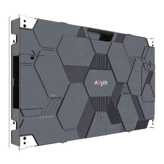
Cabinet Introduction
Product Component Drawing
Mounting Frame: Used for Wall Mounting, Including Single and Double Frames
Connector Plates and Bolts Are Used for Installations with Steel Structure
Flatness Adjusting Screw
Wire
Standard Packaging
Product Installation
Mounting Frame Installation
Connecting Plate Installation
Flatness Adjustment Mechanism
Three-Axis and Six-Way Adjustment(Cabinet)
Three-Axis and Six-Way Adjustment(Module)
Product Cabling
Power Supply Wiring
Signal Cable Wiring
Schematic Diagram of System Connection Topology
Power-On Test
Maintenance
Preparation Tools
Maintenance Instructions
Module Maintenance
HUB Board/Receiving Card/Power Supply Maintenance
Common Faults and Troubleshooting
Advertisement
Quick Links
1
Table of Contents
2
Product Introduction
3
Product Specifications
Download this manual
New HC Series User Manual
Shenzhen Absen Optoelectronic Co.,Ltd.
Table of
Contents
Previous
Page
Next
Page
1
2
3
4
5
Advertisement
Table of Contents
Need help?
Do you have a question about the HC Series and is the answer not in the manual?
Ask a question
Questions and answers
Related Manuals for Absen HC Series
Monitor Absen HC1.5 II User Manual
(24 pages)
Monitor Absen N4 User Manual
N series, indoor fixed mounted high-definition display with unique competitive advantage (20 pages)
Monitor Absen AX Series User Manual
(22 pages)
Monitor Absen X3 User Manual
(18 pages)
Monitor Absen CR Series User Manual
(19 pages)
Monitor Absen PL Lite Series User Manual
(30 pages)
Monitor Absen K Series User Manual
(17 pages)
Monitor Absen N Plus Series User Manual
(27 pages)
Monitor Absen A27 Plus Series User Manual
(25 pages)
Monitor Absen A27 Pro Series User Manual
(23 pages)
Monitor Absen K Plus Series User Manual
(22 pages)
Monitor Absen NX Series User Manual
(52 pages)
Monitor Absen JP Series User Manual
(18 pages)
Monitor Absen KLCOB V2 Series User Manual
(24 pages)
Monitor Absen AX Series User Manual
(17 pages)
Monitor Absen A99 Series User Manual
(20 pages)
This manual is also suitable for:
Hc0.7 pro ii
Hc0.9 pro ii
Hc1.2 pro ii
Hc1.2 ii
Hc1.5 ii
Table of Contents
Print
Rename the bookmark
Delete bookmark?
Delete from my manuals?
Login
Sign In
OR
Sign in with Facebook
Sign in with Google
Upload manual
Upload from disk
Upload from URL


Need help?
Do you have a question about the HC Series and is the answer not in the manual?
Questions and answers