Table of Contents
Advertisement
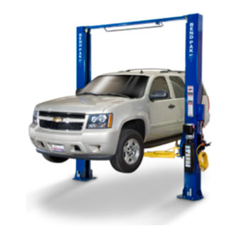
INSTALLATION AND OPERATION MANUAL
10,000 POUND CAPACITY
12,000 POUND CAPACITY
15,000 POUND CAPACITY
18,000 POUND CAPACITY
SURFACE MOUNTED
TWO-POST LIFTS
MODELS:
XP-10C
XP-10CX
XP-10AC
XP-10ACX
XP-12CTA
XP-15C
XP-18C
Keep this operation manual near the
machine at all times. Make sure that
ALL USERS read this manual .
S S H H I I P P P P I I N N G G D D A A M M A A G G E E C C L L A A I I M M S S
When this equipment is shipped, title passes to the
purchaser upon receipt from the carrier. Consequently,
claims for the material damaged in shipment must be made
by the purchaser against the transportation company at the
time shipment is received.
PLEASE READ THE ENTIRE CONTENTS OF THIS MANUAL PRIOR TO
INSTALLATION AND OPERATION. BY PROCEEDING YOU AGREE THAT YOU
FULLY UNDERSTAND AND COMPREHEND THE FULL CONTENTS OF THIS
MANUAL. FORWARD THIS MANUAL TO ALL OPERATORS. FAILURE TO
OPERATE THIS EQUIPMENT AS DIRECTED MAY CAUSE INJURY OR DEATH.
B B E E S S A A F F E E
Your new lift was designed and built with safety in
mind. However, your overall safety can be increased
by proper training and thoughtful operation on the part
of the operator. DO NOT operate or repair this equip-
ment without reading this manual and the important
safety instructions shown inside.
Santa Paula, CA. 93060, USA
REV B 10-24-07
1645 Lemonwood Dr.
Toll Free 1-800-253-2363
Tel: 1-805-933-9970
Fax: 1-805-933-9160
Advertisement
Table of Contents

Related Manuals for BendPak XP-10CX


Summary of Contents for BendPak XP-10CX
- Page 1 10,000 POUND CAPACITY 12,000 POUND CAPACITY 15,000 POUND CAPACITY 18,000 POUND CAPACITY SURFACE MOUNTED TWO-POST LIFTS MODELS: XP-10C XP-10CX XP-10AC XP-10ACX XP-12CTA XP-15C XP-18C Keep this operation manual near the machine at all times. Make sure that ALL USERS read this manual .
-
Page 2: Product Warranty
PRODUCT WARRANTY BendPak Two Post Lifts are warranted for five years on equipment structure, to be free of defects in material and work- manship. Power units, hydraulic cylinders, and all other assembly components such as turnplates, slip plates, cables, chains, valves, switches etc. - Page 3 Our willingness to practices which may result in minor personal injury, assist in helping you process your claim does not make product or property damage. BendPak responsible for collection of claims or replace- ment of lost or damaged materials.
-
Page 4: Parts Inventory
When removing the lift from shipping angles pay close attention as the posts can slide and can cause injury. Prior to removing the bolts make sure the posts are held securely by a fork lift or some other heavy lifting devise. PARTS INVENTORY QTY. - Page 5 SHIPMENT PARTS QTY. PART(S) DESCRIPTION Part Number WHERE USED CHECK AB-1466 Power Unit 5585079 Hydraulic Power Source ______ Powerside Column 5210008 Powerside Column ______ Offside Column 5210011 Offside Column ______ Top Trough see table Overhead Beam ______ Lift Arms see table Lift Arms ______ Hose and Cable Chart...
- Page 6 5595113 3/32 x 287 Safety Cable 3/32 x 300 Safety Cable Top Trough 5210003 5210114 Top Trough Assy XP-10C Top Trough Assy XP-10CX XP-10AC XP-10ACX Power Unit Hose 5570102 5570102 3/8 x 48 Power Unit Hose 3/8 x 48 Power Unit Hose...
-
Page 7: Installer / Operator Protective Equipment
Eye protection is essential during installation and opera- I understand that Bendpak lifts are designed to be tion activities. Safety glasses with side installed in indooor locations only. Failure to follow instal-... -
Page 8: Important Safety Instructions
INTRODUCTION 1. Carefully remove the crating and packing materials. 2. Check the voltage, phase and proper amperage CAUTION! Be careful when cutting steel banding requirements for the motor shown on the motor plate. material as items may become loose and fall causing per- Wiring should be performed by a certified electrician only. -
Page 9: Concrete Specifications
Rotary Hammer Drill Or Similar Medium Crescent Wrench 3/4" Masonry Bit Medium Pipe Wrench Hammer Crow Bar For Shim Installation 4 Foot Level Chalk Line Open-End Wrench Set: 7/16" - 1-1/8" Medium Flat Screwdriver Socket And Ratchet Set: 7/16" - 1-1/8" Tape Measure: 25 Foot Minimum Hex-Key / Allen Wrench Set Needle Nose Pliers... - Page 10 FLOORPLAN/ CAPACITY Model Capacity XP-10C 132” 10,000 LBS XP-10CX 145” 10,000 LBS XP-12CTA 155” 12,000 LBS XP-15C 155” 15,000 LBS XP-18C 155” 18,000 LBS Model Capacity XP-10AC 132” 10,000 LBS XP-10ACX 145” 10,000 LBS...
- Page 11 COMPLETE THE FOLLOWING PRIOR TO STANDING COLUMNS. (1) Route the plug end of each equalizer cables around the bottom pulley and lock into bottom plate When removing the lift from shipping of carriage. (Fig. 2) Feed threaded end up through angles pay close attention as the posts carriage.
- Page 12 2. Install the cylinder fittings in cylinder ports so 5. Route both hoses in their respective columns that each fitting points towards the entrance side PRIOR to raising columns to their vertical position. of lift. ( Fig 3 ). When routing the hydraulic hose through the columns, make sure to route through the retaining clips welded inside each column.
- Page 13 STEP FOUR ( Installing The POWERSIDE Column ) Fig 6 1. Before proceeding, double the check meas- urements and make certain that the bases of each column are aligned with the chalk line. 2. Using the base plate on the POWERSIDE column as a guide, drill each anchor hole in the concrete ( approximately 4-1/2”...
- Page 14 6. With the shims and anchor bolts in place, tighten Important Note by securing the nut to the base then turning 2 - 3 full turns clockwise. DO NOT use an impact wrench for YOU MUST POSITION THE SWITCH ENCLO- this procedure.
- Page 15 STEP SEVEN ( Mounting The POWER UNIT ) 1. Attach the power unit to the POWERSIDE COLUMN using four M8 hex bolts and nuts ALL WIRING MUST BE PERFORMED BY A supplied. Fill the reservoir with 10 WT. CERTIFIED ELECTRICIAN HYDRAULIC OIL OR DEXRON TYPE III ATF, approximately four gallons.
- Page 16 STEP EIGHT ( Installing the safeties and safety cable ) 1. Install safety weldments into each respec- tive post. (Fig 11 & 12) Fig 11 Fig 12...
- Page 17 Fig 13 2. From the offside column insert the non looped end of the safety cable through the hole located to the right of the offside safety weldment. (Fig 13) 3.Route the cable under the pulley and take it up to the Top Trough. (Fig 14) 4.
- Page 18 Fig 15 Fig 16 Note: Assymetrical models have an additional safety pulley to route the cable out of the path of the cylinder Fig 17 5. Route the cable the same way on the power side going back down the post. 6.
- Page 19 STEP NINE ( Installing The HYDRAULIC LINES. ) 1. Install the Bulkhead Tee fitting into the Make sure that the safety locks on powerside post. The through hole is locat- ed approximately 90 inches from the floor each column are fully engaged before on the back wall of the powerside post.
- Page 20 WARNING! WHEN THE CABLE ADJUSTING NUTS BOTTOM OUT ON THE THREADED END OF THE CABLE CONNECTOR AND THERE IS STILL SLACK IN THE CABLES, THE CABLES HAVE STRETCHED BEYOND THE SAFE USEFUL LENGTH AND NEED TO BE REPLACED WITH FACTORY APPROVED CABLE ASSEMBLIES. DO NOT PLACE WASHERS, SPACERS OR OTHER DEVICES TO “SHORTEN”...
- Page 21 DANGER! DO NOT PERFORM ANY MAINTENENCE OR INSTALLATION OF ANY COMPONENTS WITH OUT FIRST ENSURING THAT ELECTRICAL POWER HAS BEEN DISCONNECTED AT THE SOURCE OR PANEL AND CANNOT BE RE-ENERGIZED UNTIL ALL MAINTENENCE AND/OR INSTALLATION PROCEDURES ARE COMPLETED. IMPORTANT POWER-UNIT INSTALLATION NOTES DO NOT run power unit with no oil.
- Page 22 STEP ELEVEN STEP TWELVE ( Installing Overhead MICRO SWITCH. ) ( Power Unit Installation and Start-Up. ) 1. Install the overhead Micro Switch as shown below. Be sure to keep wire clear of moving parts. WIRING MUST BE PERFORMED BY A CERTIFIED ELECTRICIAN.
- Page 23 IMPORTANT NOTE: The equalizer cables should be checked weekly for equal tension. Failure to do this will cause uneven lifting. The cables should always be adjusted so that they are equal tension when resting on the safety locks.
- Page 24 You MUST re-install top carriage-stop bolt (shown below) after top beam/plate is installed and secured. Tighten carriage-stop bolt to 20 ft. lbs.of torque upon final installation inspection. These instructions must be followed to insure proper installation and operation of your lift. Failure to comply with these instructions can result in serious bodily injury and or death and or void product warranty.
-
Page 25: Post-Installation Check-Off
POST-INSTALLATION CHECK-OFF Columns Properly Shimmed And Stable Anchor Bolts Tightened WARNING! Pivot / Sheave Pins Properly Attached WHEN THE CABLE ADJUSTING NUTS BOTTOM OUT Carriage Stop bolts Torqued to 20 Ft. Lbs ON THE THREADED END OF THE CABLE Electric Power Supply Confirmed CONNECTOR AND THERE IS STILL SLACK IN THE Cables Adjusted Properly CABLES, THE CABLES HAVE STRETCHED BEYOND... - Page 26 STEP FOURTEEN ( Installation Of SAFETY COVER. ) 1. After safeties have been adjusted and checked for proper operation, install the two cover plates as shown below. ( See Fig. 24 & 25)
- Page 27 3. Lower the lift only HALF WAY by pressing the LUBRICATION SAFETY RELEASE handle inward then pressing 1. After installation and start up has been in the DOWN lever on power unit. completed, lubricate lift components described below. ( See Fig. 26 ) 4.
-
Page 29: Operation
OPERATION Push the powerside safety handle and HOLD. To Raise Lift; Push the LOWERING HANDLE on the power unit until Load vehicle onto the lift using Vehicle Lifting Guide to the lift has descended completely. determine proper lifting points. WEEKLY MAINTENANCE Lubricate all rollers with general purpose oil or WD-40. -
Page 30: To Raise Lift
TO RAISE LIFT Read operating and Safety manuals before using lift. Always lift a vehicle according to the manufactures recommended lifting points. Position vehicle between columns. Adjust swing arms so that the vehicle is positioned with the center of gravity midway between pads. Use truck adapters as needed. - Page 31 Safe Lift Operation Automotive and truck lifts are critical to the operation and profitability of your business. The safe use of this and other lifts in your shop is critical in preventing employee injuries and damage to customer’s vehicles. By operating lifts safely you can insure that your shop is profitable, productive and safe.
- Page 32 DO NOT Leave the controls while the lift is still in motion. DO NOT stand directly in front of the vehicle or in the bay when vehicle is being loaded or driven into position. DO NOT Go near vehicle or attempt to work on the vehicle when being raised or lowered. REMAIN CLEAR of lift when raising or lowering vehicle.
- Page 34 WIRE ROPE INSPECTION AND MAINTENANCE Lifting cables should be replaced every three - five years or when visible signs of damage are apparent. DO NOT USE LIFT WITH DEFECTIVE / WORN CABLES. Lifting cables should be maintained in a well-lubricated condition at all times. Wire rope is only fully protected when each wire strand is lubricated both internal and external.
- Page 36 LIFT WILL NOT RAISE POSSIBLE CAUSE 1. Air in oil, (1,2,8,13) 2. Cylinder binding, (9) 3. Cylinder leaks internally, (9) 4. Motor run backward under pressure, (11) 5. Lowering valve leaks, (3,4,6,10,11) 6. Motor runs backwards, (7,14,11) 7. Pump damaged, (10,11) 8.
-
Page 37: Motor Will Not Run
MOTOR WILL NOT RUN POSSIBLE CAUSE Fuse blown, (5,2,1,3,4) Limit switch burned out, (1,2,3,4) Microswitch burned out, (1,2,3,4) Motor burned out, (1,2,3,4,6) Voltage to motor incorrect, (2,1,8) REMEDY INSTRUCTION Check for correct voltage ......Compare supply voltage with voltage on motor nametag. - Page 38 WILL NOT RAISE LOADED LIFT POSSIBLE CAUSE 1. Air in oil, (1,2,3,4) 2. Cylinder binding, (5) 3. Cylinder leaks internally, (5) 4. Lift overloaded, (6,5) 5. Lowering valve leaks, (7,8,1,5,9) 6. Motor runs backwards, (10,12,9) 7. Pump damaged, (5,9) 8. Pump won’t prime, (1,2,3,4,5,11,9) 9.
- Page 39 LIFT WILL NOT STAY UP POSSIBLE CAUSE 1. Air in oil, (1,2,3) 2. Check valve leaks, (6) 3. Cylinders leak internally, (7) 4. Lowering valve leaks, (4,5,1,7,6) 5. Leaking fittings, (8) REMEDY INSTRUCTION 1. Check oil level ........The oil level should be up to the bleed screw in the reservoir with the lift all the way down.
- Page 52 For Parts or Service Contact: BendPak Inc. / Ranger Products 1645 Lemonwood Dr. Santa Paula, CA. 93060 Tel: 1-805-933-9970 Toll Free: 1-800-253-2363 Fax: 1-805-933-9160 www.bendpak.com www.rangerproducts.com...
Need help?
Do you have a question about the XP-10CX and is the answer not in the manual?
Questions and answers