Table of Contents
Advertisement
Quick Links
Download this manual
See also:
Service Manual
Advertisement
Table of Contents

Related Manuals for Acer Altos G310


Summary of Contents for Acer Altos G310
- Page 1 Acer Altos G310 User’s guide...
- Page 2 Changes may be made periodically to the information in this publication without obligation to notify any person of such revision or changes. Such changes will be incorporated in new editions of this manual or supplementary documents and publications. This company makes...
-
Page 3: Fcc Notice
Notices FCC notice Class A devices do not have an FCC logo or FCC IDE on the label. Class B devices have an FCC logo or FCC IDE on the label. Once the class of the device is determined, refer to the following corresponding statement. -
Page 4: Laser Compliance Statement
Notice: Peripheral devices Only peripherals (input/output devices, terminals, printers, etc.) certified to comply with the Class A or Class B limits may be attached to this equipment. Operation with noncertified peripherals is likely to result in interference to radio and TV reception. -
Page 5: Important Safety Instructions
This product should be operated from the type of power indicated on the marking label. If you are not sure of the type of power available, consult your dealer or local power company. Do not allow anything to rest on the power cord. Do not locate this product where persons will walk on the cord. - Page 6 If the product exhibits a distinct change in performance, indicating a need for service. 12 Replace the battery with the same type as the product's battery we recommend. Use of another battery may present a risk of fire or explosion. Refer battery replacement to a qualified service technician.
-
Page 7: Table Of Contents
I/O ports Serial ATA ports Caring features Product specification summary 2 System tour System board Mainboard layout Jumper settings (JP8) clear CMOS External and internal structure Front bezel Front panel Rear panel Internal components 3 Getting Started Setting up the system... - Page 8 Configuring the SCSI/SCSI RAID HBA How to use SCSI HBA setup utility Loading HBA Default Settings How to use SCSI RAID HBA setup utility How To Create RAID 1 (Mirror) volume with a Hot Spare Disk RAID Volume Initialization Exit and Restart the server...
- Page 9 ATA Operate Mode BIOS configuration Using the Intel RAID Option ROM Creating, Deleting and Resetting RAID Volumes 64 Installation of Intel Application Accelerator RAID Utility71 RAID migration instructions Create RAID Volume from Existing Disk 5 BIOS setup BIOS setup Entering BIOS setup...
- Page 10 Contents...
-
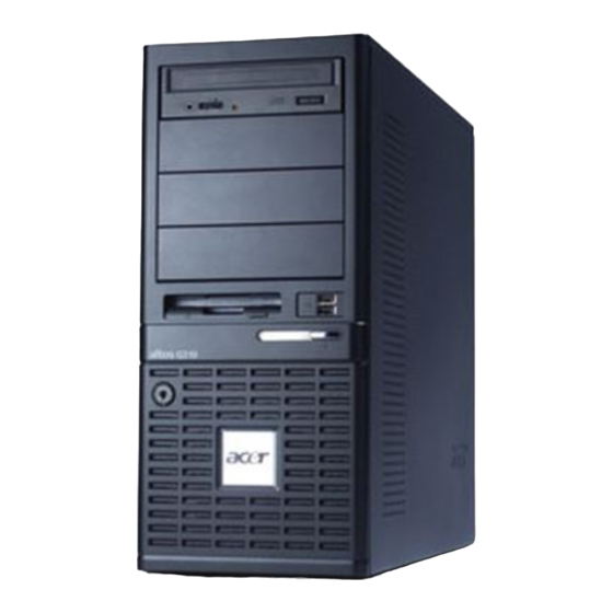
Page 11: System Information
1 System information... - Page 12 The Acer Altos G310 series server is an entry level single-processor general purpose system. The system offers a new standard for flexible productivity ideal for small business or workgroup applications.
-
Page 13: Product Briefing
AVOID using modules from different manufacturers or that run at different speeds from each other. Note: To run 400 MHz memory at full speed requires a processor with 800 MHz system bus frequency. Note: To run 333 MHz memory at full speed requires a processor... -
Page 14: Storage
1 System information Note: 333 MHz memory will run at 320 MHz when used with a processor with 800 MHz system bus frequency. Storage • 5.25 inch IDE CD-ROM drive • 3.5 inch Floppy disk drive • Support for three (max) hard disk drives •... -
Page 15: Serial Ata Ports
Serial ATA ports • Two serial ATA ports • Support RAID 0 or RAID 1 ® XP/2000/Server Note: Serial ATA supports drivers for Windows 2003 only. -
Page 16: Caring Features
1 System information Caring features Part of Acer’s mission, as a company that cares about its end users, is to provide features that make operation, maintenance, and upgrading your system simpler and faster. The Altos G310 is no exception to this rule. -
Page 17: Product Specification Summary
Highlighted below are the system’s key features: ® ® • Single Intel Pentium 4 processor supporting Hyper-Threading Technology • 533/800 MHz FSB supports processor speeds from 2.8 GHz to 3.4 • Intel ® 875P chipset consisting of: ® • Intel 82875P Memory Controller Hub (MCH) ®... - Page 18 1 System information...
-
Page 19: System Tour
2 System tour... - Page 20 This chapter provides locations of various components and ports and you instructions on how to set up the system. Procedures on how to connect peripherals are also explained.
-
Page 21: System Board
System board Mainboard layout The mainboard becomes accessible once you open the system. It should look like the figure shown below... - Page 22 Floppy disc drive connector Front panel header Buzzer connector PS/2 KBMS Serial and Parallel ports Dual USB and RJ45 Extended interface Power port and 12V power connector Main power connector Clear CMOS C feature connector PCI1 PCI slots PCI2 PCI3...
- Page 23 Item Description SYSFAN1 System fan connectors SYSFAN2 LAN controller Clock generator CPU slot (478 pin) 875P chipset ICH5R chipset I/O controller BIOS Mini-BMC USB1 Front USB connector USB2 Dual USB connector...
-
Page 24: Jumper Settings (Jp8) Clear Cmos
2 System tour Jumper settings (JP8) clear CMOS Pin Number Pin Definition Normal Clear Ground Normal Clear CMOS... -
Page 25: External And Internal Structure
External and internal structure Front bezel Note: One pair of system keys are provided (attached to the rear panel of the system). Description CD-ROM drive CD-ROM headphone port CD-ROM volume control CD-ROM activity indicator... - Page 26 2 System tour Description FDD eject button FDD (floppy disc drive) FDD activity indicator Security keylock System power indicator System power button USB 2.0 ports (two) 5.25-inch half-height bays CD-ROM stop/eject button...
-
Page 27: Front Panel
Front panel Description CD-ROM drive CD-ROM headphone port CD-ROM volume control CD-ROM activity indicator FDD eject button FDD (floppy disc drive) FDD activity indicator... - Page 28 2 System tour Description Security keylock System power indicator System power button USB 2.0 ports (two) 5.25-inch half-height bays CD-ROM stop/eject button...
-
Page 29: Rear Panel
Rear panel Icon Description Main power supply unit PS/2 mouse port PS/2 keyboard port Parallel/printer port Serial ports (two) USB 2.0 ports (four) - Page 30 2 System tour Icon Description Gigabit LAN port (10/100/1000 Mbps) AGP add-on card (actual ports vary by configuration) Side panel tool-less screws (top and bottom) System ventilation/fan exhaust Main power supply fan-exhaust...
-
Page 31: Internal Components
Internal components Description Power supply unit System fan Mainboard PCI bus slots HDD bays 3.5” device bays 5.25” device bays... - Page 32 2 System tour...
-
Page 33: Getting Started
3 Getting Started... - Page 34 This chapter gives information on setting up and starting to use your system...
-
Page 35: Setting Up The System
Acer Altos G310 series Accessory box • System keys (attached to the rear panel of the system) If any of the above items are damaged or missing, contact your dealer immediately. Save the boxes and packing materials for future use. -
Page 36: System Startup
After making sure that you have properly set up the system and connected all the required cables, you can now power on the system. To power on the system, press the power button on the front panel. The system starts up and displays a welcome message. After that, a series of power-on self-test (POST) messages appears. -
Page 37: Turning Off The System
Turning off the system To turn off the server, on the Windows task bar click on the Start button, point to Shut Down..., select Shut down from the drop- down window then click on OK. You can then turn off all peripherals connected to your server. -
Page 38: Bios Post Checkpoint Codes
Perform keyboard controller BAT test. Checks if waking up from power management suspend state. Save power-on CPUID value in scratch CMOS. Go to flat mode with 4 GB limit and GA20 enabled. Verify the bootblock checksum. Disable CACHE before memory detection. Execute full memory sizing module. -
Page 39: Bootblock Recovery Codes
The Bootblock recovery code gets control when the BIOS determines that a BIOS recovery needs to occur because the user has forced the update or the BIOS checksum is corrupt. The following table describes the type of checkpoints that may occur during the Bootblock recovery portion of the BIOS. - Page 40 Search for pre-defined recovery file name in root directory. Recovery file not found. Start reading FAT table and analyze FAT to find the clusters occupied by the recovery file. Start reading the recovery file cluster by cluster. Disable L1 cache.
-
Page 41: Post Code Checkpoints
POST code checkpoints The POST code checkpoints are the largest set of checkpoints during the BIOS pre-boot process. The following table describes the type of checkpoints that may occur during the POST portion of the BIOS Checkpoint Code Description Disable NMI, Parity, video for EGA, and DMA control- lers. - Page 42 Detects the presence of Keyboard in KBC port. Testing and initialization of different Input Devices. Also, update the Kernel Variables. Traps the INT09h vector, so that the POST INT09h han- dler gets control for IRQ1. Uncompress all available language, BIOS logo, and Silent logo modules.
- Page 43 Initializes DMAC-1 and DMAC-2. Initialize RTC date/time. Test for total memory installed in the system. Also, Check for DEL or ESC keys to limit memory test. Dis- play total memory in the system. Mid POST initialization of chipset registers. Detect different devices (Parallel ports, serial ports, and coprocessor in CPU, etc.) successfully installed in...
- Page 44 Clean-up work needed before booting to OS. Takes care of runtime image preparation for differ- ent BIOS modules. Fill the free area in F000h segment with 0FFh. Initializes the Microsoft IRQ Routing Table. Prepares the runtime language module. Disables the system configuration display if needed.
-
Page 45: Beep Codes
Beep Codes Beep codes are used by the BIOS to indicate a serious or fatal error to the end user. Beep codes are used when an error occurs before the system video has been initialized. Beep codes are generated by the system board speaker. The following table... - Page 46 3 Getting Started...
-
Page 47: Configuring The System
4 Configuring the system... - Page 48 This chapter discusses the precautionary measures and installation procedures you need to know when upgrading the system.
-
Page 49: Upgrading The System
CPU, the memory, and the expansion cards. However, for safety purposes, we do not recommend that you perform these upgrades yourself. If you want to replace or upgrade any of these components, contact your dealer or a qualified service technician for assistance. -
Page 50: Installation Precautions
Do not remove a component from its protective packaging until you are ready to install it. Wear a wrist grounding strap and attach it to a metal part of the server before handling components. If a wrist strap is not available, maintain contact with the server throughout any procedure requiring ESD protection. -
Page 51: Preinstallation Instructions
Preinstallation instructions Always observe the following before you install any component: Turn off the system and all the peripherals connected to it. Unplug all cables from the power outlets. Open the system according to the instructions on page 42. Follow the ESD precautions described in this section when handling a server component. -
Page 52: Opening The Server
4 Configuring the system Opening the server Caution! Before you proceed, make sure that you have turned off your system and all peripherals connected to it. Read the “Preinstallation instructions” on page 41. You need to open the server before you can install additional components. -
Page 53: To Remove The Side Panel
To remove the side panel The side panel is attached to the server by two (non-removable) thumbscrews. To remove the side panel: Locate the System Keys (if necessary) and unlock the system lock on the front panel. Loosen the thumbscrews located at the rear end of the left panel (1). -
Page 54: To Remove The Front Panel
4 Configuring the system To remove the front panel The front bezel is attached to the chassis by screwless hinges. To remove the front panel, you must remove the side panel first. To remove the front bezel: With your finger, pull the Front Panel Release lever located at the bottom front inside the chassis (1). -
Page 55: Installing And Removing Storage Devices
CD-ROM drive or a tape drive. To install a 5.25-inch storage device Note: If you are installing a new drive in an empty drive bay, skip steps 2 to 4. Observe the ESD precautions and pre-installation procedures described on page 41. - Page 56 Transfer the two tool-less locking rails (on either side of the old drive) to the new drive module. Insert the new CD-ROM drive into the drive bay until it locks into place with an audible “click.” Connect the power and IDE cables to the new drive.
-
Page 57: Upgrading The Cpu
This section includes instructions for removing and installing a CPU. To remove a CPU with heatsink Before installing a new CPU in a socket, remove first any previously installed CPU from that socket. Important: Before removing a CPU from the mainboard, make sure to create a backup file of all important data. - Page 58 Lift the CPU locking lever until it is fully extended. Gently unseat and pull the CPU from the socket. Warning! The heatsink becomes very hot when the system is on. NEVER touch the heatsink with any metal or with your hands.
-
Page 59: To Install A Cpu With Heatsink
40. Locate the CPU socket on the mainboard. Align the CPU to its socket, making sure that pin 1 (indicated by the notched corner) of the CPU connects to hole 1 of the socket (on the right corner in the image below). - Page 60 4 Configuring the system After locking the CPU in place, follow the two remaining steps to replace the heatsink and fan. Replace the heatsink on top of the CPU. Replace the locking levers by pressing down (1) and securing the clips (2) to lock the heatsink assembly in place.
-
Page 61: Upgrading The System Memory
Upgrading the system memory Memory configuration This section includes instructions for removing and installing a memory module. These tables (above and below) summarize the characteristics of 1-way and 2-way memory interleave configurations with and without use of dynamic mode. Throughput level... -
Page 62: To Remove A Dimm
4 Configuring the system To remove a DIMM Before installing a new DIMM in a socket, remove first any previously installed DIMM from that socket. Important: Before removing any DIMM from the mainboard, make sure to create a backup file of all important data. -
Page 63: To Install A Dimm
DIMMs must be installed in the following order: DM1. DM2, DM3 and DM4 Note: The DIMM socket is slotted to ensure proper installation. If you insert a DIMM but it does not fit easily into the socket, you may have inserted it incorrectly. Reverse the orientation of the DIMM and insert it again. -
Page 64: Installing An Expansion Card
Observe the ESD precautions and pre-installation procedures described on page 40. Remove the Side panel to access the mainboard. See page 43 for more information. Locate an empty expansion slot on the mainboard. Remove the tool-less the card bracket lock(1). - Page 65 Pull out the card bracket (2). Remove the expansion card from its protective packaging. Align the card in the empty slot on the mainboard.
- Page 66 4 Configuring the system Insert the bracket with the card into the selected slot (3). Make sure that the card is properly seated. Secure the card with the tool-less bracket card lock removed in step three above (4). 10 Observe the post-installation instructions described on page 41.
-
Page 67: Installing And Removing A Hard Disk
Follow these steps to replace your computer’s hard disk: Remove the side and front panels (see page 43 and page 44). Detach the cables from the exposed end of the HDD (1) and (2). Squeeze the two locking tabs that secure the drive to the chassis... -
Page 68: To Install A Hard Disk
Remove the side panel (see page 43). Attach the HDD rails to the sides of the drive housing. Insert the drive into an empty HDD slot (slot 1 or slot 3) until it locks into place with an audible “click” (1). -
Page 69: Configuring The Scsi/Scsi Raid Hba
LSI Logic 20320-R or LSI Logic 22320-R U32 SCSI controllers. How to use SCSI HBA setup utility During the Power-On Self Test (POST), press <Ctrl > + <C> to enter the LSI Logic Configuration Utility. Loading HBA Default Settings In the LSI Logic MPT SCSI Setup Utility, please press F2 and select Global Properties. -
Page 70: Raid Volume Initialization
4 Configuring the system Note: In the Hot Spare field, if you change settings, you will see the following messages. Press the DELETE key to ignore it. WARNING: Data on drive will be LOST! Press DELETE if data loss OK or any other key to cancel. -
Page 71: Megaraid Configuration Utility
Add 2 drives to current array and press <Enter> to finish creating current array. Press <F10> to configure the logical drives. The default RAID level for 2 disk drives is RAID1. Just select Accept to use the default setting and press <Enter> to return to the ARRAY SELECTION MENU. -
Page 72: Assign Hot Spare Disk
Select Add/View Configuration from Configuration menu. Press arrow keys to choose specific physical drives and press <F4> to set the drive as Hot Spare Disk. Select YES to confirm and the indicator for selected drive change from READY to HOTSP. -
Page 73: Configuring Parallel Ata And Serial Ata Devices
Configuring Parallel ATA and Serial ATA devices ATA Operate Mode There are two modes to choose from: Legacy mode and Native mode. Legacy Mode • System BIOS assigns 14 and 15 IRQs for HDD use • Older OSs that do not support Native Mode (DOS, Win2K, Win98/ ME...) should set S-ATA and P-ATA to Legacy Mode... -
Page 74: Intel Ich5R Serial Ata Raid Introduction
Intel ICH5R Serial ATA RAID introduction The south bridge ICH5R provides a hybrid solution that combines two independent SATA ports for support of up to two Serial ATA (Serial ATA RAID) drives. Serial ATA (SATA) is the latest generation of the ATA interface. SATA hard drives deliver transfer speeds of up to 150MB/sec. - Page 75 Power-On Self Test (POST), the following screen will appear for a few seconds: Note: The “Drive Model,” “Serial #,” and “Size” shown in the above example may differ from your system configuration. When the above message appears, press <Ctrl> + <I> simultaneously to enter the RAID Configuration Utility.
- Page 76 <Enter>. The following screen will appear: Note: The following procedure is only available with a newly-built system or if you are reinstalling your OS. It should not be used to migrate an existing system to RAID 0. Specify a RAID Volume name and then press the <TAB> or <Enter> key...
- Page 77 128 KB - Best performance for most desktops and workstations The default strip size is 128 KB. From the Strip size, press the <Tab> or <ENTER> key to advance to the Create Volume prompt. The window will appear as follows:...
- Page 78 Press <Enter> to create the specified volume and the following prompt will show: Press <Y> to confirm the selection or press <N> to previous screen to create the RAID volume again. Then you will return to the main menu with an updated status as...
- Page 79 Scroll to option 4 Exit and press <Enter> to exit the RAID Configuration utility. The following prompt appears: Press <Y> to confirm and exit or <N> to previous screen. Option 2: Delete RAID Volume Here you can delete the RAID volume, but please note that all data including settings on RAID drives will be lost.
- Page 80 4 Configuring the system Select option 2 Delete RAID Volume from the main menu window and press <Enter> to select a RAID volume for deletion. The following window will appear: Select a volume and press <Del> to delete the RAID volume. The following prompt appears: Press <Y>...
- Page 81 Press <Y> key to accept the selection. Note: You will lose all data on the RAID drives and any internal RAID structures when you perform this operation. Note: This operation may cause some issues such as incompatible RAID configuration, a failed volume or failed disk.
- Page 82 4 Configuring the system Insert the Acer System CD and click on the "Intel IAA RAID Edition" to install the software. The InstallShield Wizard will automatically begin the installation process. Click on the Next button to proceed from the installation welcome...
- Page 83 After reading the license agreement in the following window, click Yes button to continue. Select the folder in which you want the program to be installed in the following window, and click Next button to start installation.
- Page 84 4 Configuring the system Select a program folder in the following window where you want Setup to add the program icon. Default is "Intel Application Accelerator RAID Edition." The following window appears to show the Intel Application Accelerator RAID Edition Setup installation progress.
-
Page 85: Raid Migration Instructions
Once the installation is complete, the following window appears. Click the Finish button to end the installation and exit the setup utility. RAID migration instructions The Intel Application Accelerator RAID Edition offers the flexibility to upgrade from a single Serial ATA (SATA) hard drive to a two drive RAID-0 configuration when an additional SATA hard drive is added to the system. -
Page 86: Create Raid Volume From Existing Disk
On a RAID Ready system, this can be determined by making a note during POST of which port (e.g. Port 0 or Port 1) the single disk is attached to. You can also use the Intel... - Page 87 • 128KB: Best performance for most desktops and workstations Before you continue to Step 3 (by clicking Next in Step 2), read the next 2 dialog boxes carefully. Please note that once you have selected Migrate in Step 3, the Intel Application Accelerator RAID Edition will...
- Page 88 It is critical that you backup all important data before selecting Yes to these dialog boxes: Confirm the creation of new RAID volume In Step 3, confirm the creation of the new RAID volume and then click Migrate: Migration Process...
- Page 89 While you can still continue using your computer during the migration process, once the migration process starts, it cannot be stopped. If the migration process gets interrupted and your system is rebooted for any reason, it will pick up the migration process where it left off.
- Page 90 4 Configuring the system...
-
Page 91: Bios Setup
5 BIOS setup... - Page 92 This chapter gives information about the system BIOS and discusses how to configure the system by changing the settings of the BIOS parameters.
-
Page 93: Bios Setup
CMOS RAM. This memory area is not part of the system RAM which allows configuration data to be retained when power is turned off. Before you run BIOS setup, make sure that you have saved all open files. The system reboots immediately after you close setup. -
Page 94: Entering Bios Setup
Note the following reminders when moving around the setup screen: • Use the Left and Right arrow keys to move to the next page or to return to the previous screen. • Use the Up and Down arrow keys to select an item. - Page 95 • Use the Enter key to display a submenu screen. Note: When a parameter is preceded by a (>), it means that a submenu screen is available. • Press F1 for General Help on using the BIOS setup. • Press F10 to save changes and close the BIOS setup.
-
Page 96: Main
The last two parameters on the screen lets you define the system’s time and date settings. The real-time clock keeps the system date and time. After setting the date and time, you do not need to enter them every time you turn on the system. As long as the internal battery remains good and connected, the clock continues to keep the date and time accurately even when the power is off. - Page 97 Parameter Description System Time Sets the time following the hour-minute-second format. Valid values for hour, minute, and second are: Hour: 00 to 23 Minute: 00 to 59 Second: 00 to 59 System Date Sets the date following the weekday-month-day- year format. Valid values for weekday, month, day,...
-
Page 98: Advanced
Warning! Be cautious in setting parameter values in the Advanced menu as any incorrect value may cause the system to malfunction. Press Enter to enter the submenu screen of the parameters shown in the screen below. -
Page 99: Peripheral Configuration
Peripheral Configuration The Peripheral Configuration submenu lets you define the parameter settings for the system’s parallel and serial ports. Parameter Description Serial Port A Serial port 1 address and IRQ (interrupt request) setting (Address/IRQ) Serial Port B Serial port 2 address and IRQ (interrupt request) setting... - Page 100 Description Parallel Port Assigns an IRQ for the parallel port. If you install an add-on card that has a parallel port whose address conflicts with the onboard parallel port, a warning appears on the screen. Check the parallel port address of the add-on card and change the address to...
-
Page 101: Ide Configuration
IDE Configuration The IDE Configuration submenu lets you define the parameter settings related to the hard disk/s. Parameter Description IDE Configuration P-ATA Mode: default setting. P-ATA device is config- ured in legacy mode. Combined Mode: allows configuration of P-ATA and S-ATA devices in legacy mode. - Page 102 5 BIOS setup Parameter Description Primary IDE Display detected device type (if any present). Master Display NONE (if none detected). Press Enter to access submenu. Primary IDE Slave Display detected device type (if any present). Display NONE (if none detected).
-
Page 103: Primary Ide Master
Primary IDE Master These items let you select the IDE hard disk parameters that the system supports. Parameter Description Option Device Type of IDE device Vendor Vendor of the selected IDE device Size Size of the selected device Type Driver type... - Page 104 Block Mode function. If supported, it allows data transfer in blocks (multiple sectors) at a rate of 256 bytes per cycle. If you set this parameter to Disabled, data transfer from and to the device occurs one sector at a time.
-
Page 105: Floppy Configuration
Floppy Configuration The Floppy Configuration submenu displays the type of floppy drive installed in the server. Parameter Description Option Floppy Drive A Floppy disk drive type 1.44 MB/1.25 MB None... -
Page 106: Pci/Pnp Configuration
5 BIOS setup PCI/PnP Configuration The PCI/PnP Configuration submenu lets you specify the settings for the PCI devices. Parameter Description Option USB Function Enables the system’s USB ports Enabled Disabled Legacy USB Enable this parameter when you intend to Disabled... - Page 107 Parameter Description Option PCI Slot-1 IRQ Sets a parameter for the PCI buses. Auto Reference thru PCI Slot-5 IRQ Reference...
-
Page 108: Boot Settings Configuration
5 BIOS setup Boot Settings Configuration The Boot Settings Configuration submenu lets you specify the preferred settings for system bootup. Parameter Description Option Quick Boot Allows the system to boot faster by Enabled skipping some POST routines. Disabled... - Page 109 Option Quiet Boot Enables or disables the Quiet Boot func- Enabled tion. When set to Enabled, BIOS setup is in Disabled graphical mode and displays only an iden- tification logo during POST and while booting. After booting, the screen displays the operating system prompt (such as DOS) or logo (such as Windows).
- Page 110 Enabled Error prompted to press F1 when an error is Disabled detected during boot up. MPS 1.4 If you enable this item, the system BIOS MP Enabled Support table will be compatible with Disabled MultiProcessor Specification version 1.4 . Memory Test...
-
Page 111: Onboard Device Configuration
OnBoard Device Configuration The OnBoard Configuration submenu displays the types of devices the system board can support. Parameter Description Option OnBoard LAN Gigabit ethernet support Enabled Disabled OnBoard S-ATA Serial ATA drive support Enabled Disabled... -
Page 112: Event Log Configuration
The Event Log Configuration submenu lets you specify the appropriate settings for the system’s event handling function. The system event log enables you to record and monitor events that occur in the system (e.g., system temperature changes, fan stops, etc.). - Page 113 ECC Event ECC (Error Correcting Code) tests the accu- Enabled Logging racy of data as it passes in and out of mem- Disabled ory. When this parameter is enabled, single-bit and multi-bit memory errors will be recorded in the event log.
-
Page 114: Remote Access Configuration
5 BIOS setup Remote Access Configuration The Remote Access Configuration submenu lets you specify settings related to the system’s remote management features. Parameter Description Option Remote Access Enables or disables remote access. Disabled Selecting Serial enables remote access Serial and opens a submenu to configure sys- tem parameters. -
Page 115: System Health Monitoring
Flow Control Selecting Hardware enables flow con- None trol of remote access. Hardware System Health Monitoring The System Health Monitoring submenu lets you check various system parameters. This information is for reference only, no parameters in this submenu can be changed. -
Page 116: Power
5 BIOS setup Power The Power menu allows you to configure the system’s power management feature. Parameter Description Option ACPI-aware O/S This parameter indicates whether the sys- tem’s OS support the ACPI (Advanced Con- figuration and Power Interface) standard of power management. - Page 117 Restore on AC Defines the power state to resume to after Last State Power Loss a system shutdown that is due to an inter- Always On ruption in AC power. When set to Last State, the system will return to the active power state prior to shutdown.
-
Page 118: Boot
5 BIOS setup Boot The Boot menu allows you to specify the preferred settings during system bootup. Press Enter to enter the submenu screen of the parameters shown in the screen below. -
Page 119: Boot Device Priority
Boot Device Priority The Boot Device Priority submenu lets you specify the boot search sequence during the POST process. BIOS setup will display an error message if the drive(s) specified is not bootable. Parameter Description 1st Boot Device Sets the device from which the system will first attempt to boot up. -
Page 120: Security
5 BIOS setup Security The Security menu allows you to safeguard and protect the system from unauthorized use by setting up access passwords. Parameter Description Option Supervisor Prevents unauthorized access to the Not Installed Password BIOS setup Installed User Password... - Page 121 Parameter Description Option Change User Press Enter to change the User pass- Password word. Clear User Press Enter to remove the User pass- Password word.
-
Page 122: Exit
5 BIOS setup Exit The Exit menu displays the various options to quit from the BIOS setup. Highlight any of the exit options then press Enter. Parameter Description Save Changes Saves changes made and close the BIOS setup and Exit... - Page 123 Loads the failsafe settings for all BIOS parameters. Defaults Failsafe settings, compared to the optimal settings, are not quite as demanding in terms of resources consump- tion so you can be sure to have a stable system perfor- mance even if you are using low-grade components. Discard Discards all changes made on the BIOS setup.
- Page 124 5 BIOS setup...
- Page 125 Appendix A: Management software installation...
- Page 126 This appendix shows you how to install the ASM and EasyBUILD software packages.
-
Page 127: Installing Asm
Installing ASM Acer Server Manager (ASM) consists of the ASM Console and the ASM Agent. These two components are both required to perform server management tasks. System requirements ASM requires TCP/IP connectivity between the ASM Console and the ASM Agent. -
Page 128: Installing Asm Agent (Windows Version)
Follow all onscreen instructions to complete installation. For detailed instructions on installing ASM Console, refer to the ASM User’s manual. To launch the program, on the Windows taskbar click on the Start button, point to programs, select Acer Server Manager then click Acer Server Manager... -
Page 129: Installing Asm Agent (Linux Version)
Installing ASM Agent (Linux version) To install the ASM6 Agent on RedHat Linux 8.0 Insert the ASM6 installation CD into your computer's optical drive. Mount the CD-ROM drive with "mount /dev/cdrom /mnt/cdrom" command. For more information on mount command and the options, please refer to RedHat Linux user's guide. - Page 130 Appendix A: Management software installation...
-
Page 131: Index
Boot Settings Configuration Event Log Configuration I/O ports install a CPU Floppy Configuration Installation precautions IDE Configuration Installing and removing storage de- Primary IDE Master vices Intel Application Accelerator RAID OnBoard Device Configura- Utility tion Intel ICH5R Serial ATA RAID... - Page 132 Opening your system SCSI HBA SCSI HBA setup package contents SCSI RAID HBA Parallel ATA and Serial ATA devices SCSI RAID HBA setup Serial ATA ports POST code checkpoints Storage Post-installation instructions system boards Preinstallation instructions mainboard layout Preinstallation requirements...
Need help?
Do you have a question about the Altos G310 and is the answer not in the manual?
Questions and answers