Table of Contents
Advertisement
Quick Links
Advertisement
Table of Contents
Troubleshooting

Related Manuals for Acer Altos G540 Series


Summary of Contents for Acer Altos G540 Series
- Page 1 Acer Altos G540 Series User’s Guide...
- Page 2 Model Name : G540 Part Number: MU.R230E.001 Purchase Date: Place of Purchase: Acer and the Acer logo are registered trademarks of Acer Inc. Other company’s product names or trademarks are used herein for identification purposes only and belong to their respective companies.
-
Page 3: Class A Equipment
Notices FCC notice Class A devices do not have an FCC logo or FCC IDE on the label. Class B devices have an FCC logo or FCC IDE on the label. Once the class of the device is determined, refer to the following corresponding statement. Class A equipment This device has been tested and found to comply with the limits for a Class A digital device pursuant to Part 15 of the FCC Rules. -
Page 4: Laser Compliance Statement
Use conditions This part complies with Part 15 of the FCC Rules. Operation is subject to the following two conditions: (1) this device may not cause harmful interference, and (2) this device must accept any interference received, including interference that may cause undesired operation. Notice: Canadian users This Class A digital apparatus meets all requirements of the Canadian nterference-Causing Equipment Regulations. -
Page 5: Important Safety Instructions
Important safety instructions Read these instructions carefully. Save these instructions for future reference. Follow all warnings and instructions marked on the product. Unplug this product from the wall outlet before cleaning. Do not use liquid cleaners or aerosol cleaners. Use a damp cloth for cleaning. Do not use this product near water. - Page 6 Unplug this product from the wall outlet and refer servicing to qualified service personnel under the following conditions: When the power cord or plug is damaged or frayed. If liquid has been spilled on the product. If the product has been exposed to rain or water. If the product does not operate normally when the operating instructions are followed.
-
Page 7: Table Of Contents
1 System tour System specifications Performance Mechanical Environmental Hardware options External and internal structure Front bezel Front panel Rear panel Internal components System boards Mainboard Backplane board SAS controller board BMC module ARMC/3 module System LED indicators Front panel LED indicators Hot-plug HDD LED indicator LAN port LED indicators Power supply module LED indicators... - Page 8 viii Installing a HDD cage Removing a HDD cage Installing an additional hard drive Configuring a 5-25 inch storage device Upgrading the processor Upgrading the system memory Installing an expansion card Installing the SAS controller board Installing the BMC module Installing the ARMC/3 module Installing a redundant power supply module 4 System BIOS...
- Page 9 5 System troubleshooting Resetting the system Initial system startup problems Initial troubleshooting checklist Hardware diagnostic testing Checking the boot-up status Verifying the condition of the storage devices Confirming loading of the operating system Specific problems and corrective actions Appendix A: Server management tools Server management overview RAID configuration utilities Onboard SATA RAID Configuration Utility...
-
Page 11: System Tour
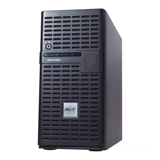
1 System tour... - Page 12 The Acer Altos G540 server is a fully modular dual-processor system featuring the latest in computing technology. It host a range of powerful and flexible features designed to meet the needs of various network environments. From simple networking functions to computing intensive applications,...
-
Page 13: System Specifications
System specifications This section lists down the impressive computing features of the Altos G540 system. Performance Processor • Two Intel LGA771 processor sockets supporting Dual-Core ® Intel Xeon™ processor • 2x 2 MB or 4 MB external L2 cache • 1066 or 1333 MHz FSB speed •... - Page 14 PCI interface • Six PCI bus slots with three separate bus segments • Three PCI Express x8 bus slots • Two 64-bit, 66/100 MHz PCI-X bus slots • One 32-bit/33 MHz PCI bus slot • One dedicated PCI-X slot for the optional SAS controller board. Video controller •...
- Page 15 Winbond W83792D hardware monitoring IC for voltage, temperature, and fan speed detection • LED indicators for constant monitoring of basic system function • Acer Server Management (ASM) monitors potential problem spots in the network environment Operating system ® • Microsoft Windows •...
-
Page 16: Mechanical
Mechanical • Chassis • Tool-less chassis design for easy hardware access and configuration • Tower and rack-mount (5U, tray-less) setup options • Dimensions – Height: 445 mm (17.5 in) – Depth: 212 mm (8.3 in) – Width: 550 mm (21.6 in) •... -
Page 17: Hardware Options
BMC (Baseboard Management Controller) module – IPMI (Intelligent Platform Management Interface) 2.0 compliant – In-band and out-band server management • ARMC/3 (Acer Remote Management Card/3) module – High performance KVM redirection – Includes a dedicated NIC port – USB mouse, keyboard, and media redirection... -
Page 18: External And Internal Structure
External and internal structure Front bezel Component Side panel release button Security keylock This lock secures the bezel door to protect the server unit from unauthorized access. LED indicator panel For more information on the LED indicators description, go to page 21. -
Page 19: Front Panel
Front panel Icon Component DVD-ROM drive Eject button DVD-ROM drive activity indicator DVD-ROM drive mechanical eject hole DVD-ROM drive 5.25-inch drive bay Power indicator HDD activity indicator Status/fault indicator Description Press this button to open the DVD drive tray. When the LED indicator is lit, there is an ongoing DVD drive activity. - Page 20 Icon Component LAN port 1/2 status indicators Hot-plug HDD activity indicator HDD cage HDD cage bay USB 2.0 ports Power button FDD Eject button Floppy disk drive FDD activity indicator 1 System tour Description Indicate the system network connection status. Indicates the status of a hot-plug HDD installed in the system (green /amber).
-
Page 21: Rear Panel
Rear panel Icon Component Power supply module release latch Power supply module cord socket Main power supply module PS/2 mouse port PS/2 keyboard port Parallel port Serial port Monitor port Description Push down the latch to disengage the module from the chassis. Connect the system power cord here. - Page 22 Icon Component Unit identification (UID) switch/ indicator USB 2.0 ports Gigabit LAN ports 1/2 PCI slot covers System fan Redundant power supply module bay Power supply module fault indicator Power supply module status indicator Description Press to mark a particular server unit within a server group (when rack-mounted) for purpose of identification during servicing or...
-
Page 23: Internal Components
Internal components Component Redundant power supply module bay Air duct Heat sink fan (HSF) assemblies Release sliders for the 5.25-inch devices Release sliders for the HDD cages Mainboard PCI slot lock levers System fan Users have the option to purchase a redundant system fan unit. -
Page 24: System Boards
1 System tour System boards Mainboard... - Page 25 Code COM1 LPT1 VGA1 — — DIMMA1 DIMMA2 DIMMB1 DIMMB2 DIMMC1 DIMMC2 DIMMD1 DIMMD2 FAN_R2 FAN_R1 ATX1 ATX3 FAN_CPU1 CPU 1 U108 CPU 2 FAN_CPU2 Description Top: PS/2 mouse port Bottom: PS/2 keyboard port Serial port Parallel/printer port Monitor port UID switch Gigabit LAN ports USB 2.0 ports...
- Page 26 Code JP_PASS1 JP_REC1 IDE1 USB1 and USB2 SATA HDD 0-5 CLR_CMOS1 BAT1 FDC1 PCI7 JP_FP1 — IPMB_6 SODIMM1 Description Clear password jumper Open – Normal (default) Close – Clear password BIOS recovery jumper 1-2 – Enable BIOS recovery 2-3 – Disable (default) IDE cable connector Front USB connectors SATA2 data cable connectors...
-
Page 27: Backplane Board
Code PCI-E 4 PCI-E 5 PCI-X 2 PCI-X 3 PCI-E 1 1 The PCI-X 3 slot (green) supports the installation of a SAS ZCR (Zero Channel RAID) option card. ackplane board The backplane board attached to rear of the hot-plug HDD cage is what differentiate it from the easy-swap HDD cage model. -
Page 28: Sas Controller Board
Code 792D_ID1 SAS/CON SATA/SAS_1-4 SAS controller board This controller board enables the installation of a SAS HDD. Code SODIMM_CON1 SAS1-1 SAS1-2 Description HDD cage ID setting jumper Close 1-2 – 5C (default for top HDD cage) Close 2-3 – 58 (default for bottom HDD cage) SAS/SATA2 HDD data cable connector Backplane board management cable connector SAS/SATA2 HDD connectors... -
Page 29: Bmc Module
BMC module The optional BMC module is the meeting point between the server hardware and the system management software. In conjunction with the mainboard hardware monitor, it allows system administrators to manage the system remotely over a network. Code Description SODIMM1 ARMC/3 module connector DIMM1... -
Page 30: Armc/3 Module
ARMC/3 module The optional ARMC/3 module expands the server’s remote management function through its own dedicated NIC port. System administrators can now have full remote access to the server regardless of its condition. Options to access server configuration, performance and storage; view a summary of key components; and monitor system health events are readily access using a simple browser. -
Page 31: System Led Indicators
LAN port 1/2 Green connection 1 The status/fault LED indicator is only enabled when the optional BMC module is installed on the mainboard. To purchase this option, contact your local Acer representative. Status Description The system has AC power and is powered on. -
Page 32: Hot-Plug Hdd Led Indicator
Hot-plug HDD LED indicator A drive activity LED indicator is mounted on the hot-plug HDD carrier. The table below lists the possible drive states. Status Green HDD access Blinking HDD failure — HDD rebuild Flashing green/amber LAN port LED indicators Indicator Color Status... -
Page 33: Power Supply Module Led Indicators
Power supply module LED indicators Indicator Color Status (top) Green Fault (bottom) Green Amber Status Description Output requirements are met. AC power is disconnected from the module. Input voltage requirements are met. • Overvoltage • Overcurrent • Output short circuit AC power is disconnected from the module. - Page 34 1 System tour...
-
Page 35: System Setup
2 System setup... - Page 36 This chapter gives you instructions on how to prepare the system for operation. Procedures for connecting peripherals are also explained.
-
Page 37: Setting Up The System
Acer Altos G540 system • Acer EasyBUILD DVD Pack • Acer Altos G540 accessory box • System keys (attached to the rear of the bezel door) If any of the above items are damaged or missing, contact your dealer immediately. -
Page 38: Connecting Peripherals
Connecting peripherals The color-coded I/O port panel on the system rear accepts a variety of compatible peripherals. Refer to the figure below for specific connection instructions for each port. Note: Consult the operating system manual for information on how to configure the network setup. Caution: Do not route the power cord where it will walked on or pinched by items placed against it. -
Page 39: Turning On The System
Turning on the system After making sure that you have properly set up the system, applied power, and connected all the necessary peripherals, you can now power on the system. Follow the procedure below. Open the bezel door. Press the power button. The system starts up and displays a welcome message on the monitor. -
Page 40: Power-On Problems
Note: If the system does not turn on or boot after pressing the power button, go to the next section for the possible causes of the boot failure. Aside from the POST messages, you can determine if the system is in good condition by checking if the following occurred. -
Page 41: Configuring The System Os
Configuring the system OS The Altos G540 comes with Acer EasyBUILD that allows users to conveniently install the preferred operating system. To start using EasyBUILD, follow the steps below. Locate the EasyBUILD DVD included in the system package. With the system turned on, press the DVD-ROM drive Eject button. -
Page 42: Rack Mount Configuration
A rack mount kit is available for customers who prefer to mount the server in a system rack. To purchase a rack mount kit, contact your local Acer representative or order directly from http://www.acer.com/. The figure below shows the Altos G540 server in a rack-mount position. -
Page 43: Turning Off The System
Turning off the system There are two ways to turn off the server—via software or via hardware. The software procedure below applies to a system running on a Windows OS. For other NOS shutdown procedures, refer to the related user documentation. To turn off the system via software: Press Ctrl+Alt+Delete on the attached keyboard or click the Start on the Windows taskbar. - Page 44 2 System setup...
-
Page 45: System Upgrade
3 System upgrade... - Page 46 This chapter discusses the precautionary measures and installation procedures you need to know when upgrading the system.
-
Page 47: Installation Precautions
Installation precautions Before you install any server component, it is recommended that you read the following sections first. These sections contain important ESD precautions along with pre-installation and post-installation procedures. ESD precautions Electrostatic discharge (ESD) can damage static-sensitive hardware components, such as the processor, disk drives, and the system boards. Always observe the following precautions before you install a server component: •... -
Page 48: Pre-Installation Instructions
Pre-installation instructions Perform the steps below before you open the server or before your remove or replace any component. Warning! Failure to properly turn off the server before you start perform any hardware configuration may cause serious damage and bodily harm. Do not attempt the procedures described in the following sections unless you are a qualified service technician. -
Page 49: Opening The Server
Opening the server Caution: Before you proceed, make sure that you have turned off the system and all peripherals connected to it. Read the “Pre-installation instructions” section on page 38. You need to open the server before you can install upgrade components. -
Page 50: Removing The Front Bezel
Removing the front bezel Remove the side panel. Refer to the previous section for instructions. Remove the front bezel. (1) Release the bezel door retention tabs from the chassis interior. (2) Pull the bezel away from the chassis. 3 System upgrade... -
Page 51: Configuring The Hard Drive
You have the option to purchase an extra HDD cage to provide the system with additional storage capacity and scalability. Contact your local Acer representative for more information. Note: The HDD cage comes with HDD dummy covers. You need to purchase a blank HDD carrier to install a hard drive. - Page 52 Install the HDD cage. (1) Slide the cage into the lower bay with the HDD carriers facing front. The cage locked to the chassis with an audible click. If you have installed a hot-plug HDD cage, proceed to next step for related drive cable connections. Drive cable connections for an easy-swap HDD can be found on page page 47.
- Page 53 (3) Connect the other end of the SAS/SATA2 cable to the SAS1-1 connector of the SAS controller board. Remove the HDD cage bay plastic cover from the front bezel. (1) Use a flat-blade screwdriver to disengage the tabs on the top edge of the cover from its bezel slots.
-
Page 54: Removing A Hdd Cage
Removing a HDD cage Perform the pre-installation instructions described on page 37. Prepare the HDD cage for removal. • For a hot-plug HDD cage, disconnect the data and power cables from the backplane board, then remove all HDDs from the cage. •... -
Page 55: Installing An Additional Hard Drive
Installing an additional hard drive The Altos G540 HDD cage models supports both SATA2 and SAS hard drives in different capacities. Note: If you intend to install a SAS hard drive model, you first need to install the SAS controller board option. For related instructions, go to page 62. - Page 56 Align the new hard disk with the HDD carrier, then secure it with the four screws you removed in step 3-1. Install the new hard drive into the cage. (1) Slide the drive into the cage with the carrier handle still extended.
- Page 57 To install an easy-swap hard drive: Remove the side panel from the chassis. Go to page 39 for instructions. Observe steps 2 through 5 of the previous section. Connect the easy-swap HDD cables. (1) Connect the power connectors of the SAS/SATA2 cable to the power supply module HDD power cables.
-
Page 58: Configuring A 5-25 Inch Storage Device
Configuring a 5-25 inch storage device The three 5.25-inch device bays support a variety of storage devices for additional storage capacity and scalability. Go to page 4 for a list of supported storage devices. By default, the system ships with a DVD-ROM drive installed on the topmost device bay, and a floppy drive on the bottom-most device bay. - Page 59 Remove the two screws that secure the cover of the empty 5.25-inch drive bay (1), then detach the cover (2). Keep this cover for future reinstallation. Install the new 5.25-inch storage device. The instructions given below apply to a regular 5.25-inch storage device.
-
Page 60: Upgrading The Processor
Upgrading the processor This section explains the procedures for removing and installing the processor and heat sink fan (HSF) assembly. Processor configuration guidelines The mainboard has two LGA771 processor sockets supporting Dual-Core Intel Xeon processors. You have the option to upgrade the default processor or install a second one for a dual-processor configuration. - Page 61 Remove the HSF assembly. Use a long-nosed screwdriver to loosen the four HSF mounting pins. (2) Once you have loosened all four mounting pins, lift the HSF away from the mainboard. (3) Lay down the HSF in an upright position—with the thermal patch facing upward.
- Page 62 (1) Use an alcohol pad to wipe off the old thermal grease from both the HSF assembly and the processor socket retention plate. (2) Apply a thin layer of an Acer-approved thermal interface material before installing the HSF. Make sure that only a very thin layer is applied so that both contact surfaces are still visible.
- Page 63 10 Reinstall the HSF assembly. (1) Align then insert the HSF on top of the retention plate. (2) Use a long-nosed screwdriver to tighten the four HSF mounting pins to secure the assembly. 11 Reconnect the HSF cable to its mainboard connector. Refer to the “Mainboard”...
- Page 64 Reinstall the HSF assembly. (1) Align then insert the HSF on top of the retention plate. (2) Use a long-nosed screwdriver to tighten the four HSF mounting pins to secure the assembly. Observe the post-installation instructions described on page 38. 3 System upgrade...
-
Page 65: Upgrading The System Memory
Channel D - DIMMD1 and DIMMD2 System memory configuration guidelines • To ensure data integrity, use only Acer-approved 240-pin, DDR2 667 FBD ECC modules in 512 MB, 1 GB, or 2 GB capacities. • Use identical modules—same specification for size, speed, and... - Page 66 • Observe the population sequence illustrated in the table below when installing a memory module. Branch 0 DIMM A1 DIMMA2 DIMMB 1 DIMMB2 DIMMC1 DIMMC2 DIMMD1 DIMMD2 512 MB 512 MB 512 MB 512 MB 512 MB 512 MB 512 MB 512 MB 512 MB 512 MB...
- Page 67 • Install FBD pair upgrades in the following sequence: – First FBD pair: DIMMA1 and DIMMB1 slots – Upgrade 1: DIMMC1 and DIMMD1 slots – Upgrade 2: DIMMA2 and DIMMB2 slots – Upgrade 3: DIMMC2 and DIMMD2 slots To remove an FBD: Important: Before removing an FBD, make sure to back up all important system files.
- Page 68 Remove the FBD. (1) Press the holding clips on both sides of the socket outward to release the DIMM. (2) Gently pull the DIMM upward to remove it from the socket. If you intend to install a new FBD, proceed to the next section for related procedure, otherwise reinstall the air duct, then observe the post-installation instructions described on page 38.
- Page 69 (2) Firmly press the holding clips inward to lock the FDB in place. If the holding clips do not close, the FBD is not properly inserted. Reinstall the air duct. Observe the post-installation instructions described on page 38. The system automatically detects the amount of memory installed. Run the BIOS setup to view the new value for total system memory and make a note of it.
-
Page 70: I/O Interface
Installing an expansion card This section explains how to install an expansion card. I/O interface Altos G540 has six PCI bus slots with of three separate bus segments, namely: • PCI-E 1, PCI-E 4, and PCI-E 5 – PCI Express x8 slots •... - Page 71 (3) Insert the card into the selected slot. Make sure that the card is properly seated. (4) Press the release latch to secure the card in place. (5) Connect the necessary cables to the expansion card as required. Observe the post-installation instructions described on page 38. When you turn on the system, the BIOS setup automatically detects and assigns resources to the new device (applicable only to Plug-and-Play expansion cards).
-
Page 72: Installing The Sas Controller Board
Installing the SAS controller board If you intend to install a SAS hard drive, you need to first install the LSI 1068 SAS controller board option. To install the SAS controller board: Perform the pre-installation instructions described on page 37. Locate the SODIMM slot. -
Page 73: Installing The Bmc Module
Installing the BMC module The optional BMC module allows system administrators to manage the Altos G540 system remotely over a network. To install the BMC module: Perform the pre-installation instructions described on page 37. Locate the IPMB_6 slot. If necessary, remove any boards or cables that prevent access to it. -
Page 74: Installing The Armc/3 Module
Installing the ARMC/3 module Remote system management just got easier with the new ARMC/3 module. The module provides high performance KVM (keyboard- video-mouse) redirection and features a dedicated NIC port for faster network access. To install the ARMC/3 module: Perform the pre-installation instructions described on page 37. Locate the IPMB_6 slot. - Page 75 Install the dedicated NIC port card. (1) Press the release latch of the slot cover opposite the IPMB_6 slot. The release latch highlighted in the figure below is for illustration purpose only. (2) Pull out the slot cover and store it for reassembly later. Caution: Do not discard the slot cover.
-
Page 76: Installing A Redundant Power Supply Module
Installing a redundant power supply module The Altos G540 supports two 610-watts hot-swap power supply modules. The system ships out with only one power supply module installed. You have the option to install a second module to provide the system with a redundant power source. A redundant power configuration enables a fully-configured system to continue running even if one of the power supply module fails. - Page 77 To install a hot-swap power supply module: Detach the cover from the chassis. Keep the cover for future reassembly. Slide the module into the empty bay until you feel resistance, and it locks into place. Verify that the power status indicators on the main power supply and on the newly installed redundant power supply are illuminated green.
- Page 78 3 System upgrade...
-
Page 79: System Bios
4 System BIOS... - Page 80 This chapter gives information about the system BIOS and discusses how to configure the system by changing the settings of the BIOS parameters.
-
Page 81: Bios Overview
BIOS overview BIOS setup is a hardware configuration program built into the system's Basic Input/Output System (BIOS). Since most systems are already properly configured and optimized, there is no need to run this utility. You will need to run this utility under the following conditions. •... -
Page 82: Entering Bios Setup
Entering BIOS setup Turn on the server and the monitor. If the server is already turned on, close all open applications, then restart the server. During POST, press F2. If you fail to press F2 before POST is completed, you will need to restart the server. -
Page 83: Bios Setup Navigation Keys
BIOS setup navigation keys Use the following keys to move around the Setup utility. • Left and Right arrow keys – Move between selections on the menu bar. • Up and Down arrow keys – Move the cursor to the field you want. -
Page 84: Main Menu
Main menu Parameter Description System Time Set the system time following the hour-minute-second format. System Date Set the date following the weekday-month-day-year format. BIOS Version Version number of the BIOS setup utility BIOS Date Date when the BIOS setup utility was created Processor Technical specifications for the installed processor CPU Type... -
Page 85: Advanced Menu
Advanced menu The Advanced menu display submenu options for configuring the function of various hardware components. Select a submenu item, then press Enter to access the related submenu screen. -
Page 86: Advanced Processor Options
Advanced Processor Options Parameter Description Processor Retest Select whether to delete the historical processor data log. Processor(s) will be retested on the next boot-up. CPU Type Processor model name CPU Speed The processor speed is the speed at which a microprocessor executes instructions. -
Page 87: Cpu Cache Control
Parameter Description Intel Select whether to enable the Intel Virtualization Virtualization Technology function. VT Technology allows a single platform to run multiple operating systems in independent partitions. C1 Enhanced Select whether to enable the C1 Enhanced Mode mode for the processor. If enabled, all logical processors in a physical processor will run in a C1 state. -
Page 88: Memory Configuration
Memory Configuration Parameter Description Extended Total size of extended memory detected during POST Memory DIMM Group The size of memory installed on each of the FBD slots. #1 - 8 Status Memory Retest Select whether to delete the historical memory data log. System memory will be retested on the next boot-up. -
Page 89: Advanced Chipset Control
Advanced Chipset Control Parameter Description Advanced Select whether to enable the system Multimedia multimedia timer. Timer Crystal Beach Select whether to enable configuration Configure /memory mapped access to the Crystal Enable Beach Configuration space. I/O Acceleration Select whether to enable the Intel Technology Acceleration Technology (I/OAT) function. -
Page 90: Pci Configuration
PCI Configuration Parameter Description PCI Slot 1 - 6 When enabled, this setting will initialize Option ROM the device expansion ROM for the related PCI slot. SAS Option When enabled, this setting will initialize the SAS controller board expansion ROM. LAN 1/2 Select whether to enable the selected Option ROM... -
Page 91: I/O Device Configuration
I/O Device Configuration Parameter Description Serial Port A/B When enabled allows you to configure the serial port settings. When set to Auto allows the server’s BIOS or OS to select a configuration. When set to Disabled, displays no configuration for the serial port. Option Enabled Disabled... - Page 92 Parameter Description Base I/O address Base I/O address and IRQ setting for the selected serial port Parallel Port When enabled allows you to configure the parallel port settings. Mode Sets the operation mode for the parallel port. When set to Bi-Directional, allows normal speed operation in a two way mode.
-
Page 93: Ide Configuration
Parameter Description Parallel ATA Select whether to enable support for PATA devices. Serial ATA Select whether to enable support for SATA devices. Native Mode Select the native mode for the SATA Operation function. SATA Controller Select whether to set SATA/PATA Mode Option devices to legacy (Compatible) or native (Enhanced) mode. -
Page 94: I/O Channel 0/Secondary Master/Slave
I/O Channel 0/Secondary Master/Slave Parameter Description Type Selects the drive type. Total Sectors Total number of sectors available in the selected hard drive. Maximum Maximum capacity of the selected hard drive. Capacity Multi-Sector Set the multi-Sector transfer mode. Transfers LBA Mode Selects the hard disk drive translation Control method. -
Page 95: Floppy Configuration
Parameter Description Transfer Select a transfer mode to enhance hard Mode disk performance. Ultra DMA Selects DMA (Direct Memory Access) Mode mode. Floppy Configuration The Floppy Configuration submenu displays the type of floppy disk drive installed in the server. Option Fast PIO 4 Standard Fast PIO 1... -
Page 96: Boot Configuration
Boot Configuration Parameter Description Boot-time Choose whether to display the boot-time Diagnostic diagnostic screen during POST. Screen Reset Select whether to erase data in the section Configuration of memory for ESCD (Extended System Data Configuration Data) which stores the configuration settings for non-PnP plug-in devices. -
Page 97: Dmi Event Logging
Parameter Description After Power Defines the power state to resume to after a Failure system shutdown that is due to an interruption in AC power. When set to Last State, the system will return to the active power state prior to shutdown. - Page 98 Parameter Description View DMI Press Enter to view the DMI (Desktop Management Event Log Interface) event log. To return to the DMI Event Logging submenu, click Continue in the Event Log window. Event Select whether to allow logging of all Logging DMI events.
-
Page 99: Security Menu
Security menu The Security menu allows you to safeguard and protect the system from unauthorized use by setting up access passwords. There are three types of passwords that you can set: • Supervisor password Entering this password will allow the user to access and change all settings in the Setup Utility. -
Page 100: Setting A System Password
Parameter Description Supervisor This parameter indicates whether a Password Is supervisor password has been assigned. User Password Is This parameter indicates whether a user password has been assigned. Set Supervisor Press Enter to configure the supervisor password. Password Set User Press Enter to configure the user password. -
Page 101: Changing A System Password
Changing a system password Use the up/down keys to select a password parameter (Set Supervisor Password or Set User Password), then press Enter. Type the original password then press Enter. Type a new password then press Enter. Retype the password to verify the first entry then press Enter again. -
Page 102: Server Menu
Server menu Parameter System Management Console Redirection Event Log Configuration Description Displays basic system ID information, as well as BIOS and BMC firmware versions. Press Enter to access the related submenu. Displays console redirection-related settings. Press Enter to access the related submenu. Displays DMI event log-related settings. -
Page 103: System Management
System Management The System Management submenu is a simple display page for basic system ID information, as well as BIOS and BMC firmware versions. Items on this window are non-configurable. Console Redirection... - Page 104 Parameter Description COM Port Select whether to enable console Address redirection. Console redirection enables users to manage the system from a remote location. Baud Rate Select the baud rate for console redirection. Console Select a terminal type to be used for Type console redirection.
-
Page 105: Event Log Configuration
Event Log Configuration Parameter Description Clear All Event Press Enter then select whether to clear all entries in Logs the system event log. Log POST Sys. Select whether to enable the BIOS event Event log to be integrated in the system event log. -
Page 106: Boot Menu
Boot menu The Boot menu allows you to set the drive priority during system boot-up. BIOS setup will display an error message if the drive(s) specified is not bootable. By default, the server searches for boot devices in the following order: Floppy disk drive Optical disc drive Removable device... -
Page 107: Exit Menu
Exit menu The Exit menu displays the various options to quit from the BIOS setup. Highlight any of the exit options then press Enter. Parameter Description Exit Saving Saves changes made and close the BIOS setup. Changes Exit Discarding Discards changes made and close the BIOS setup. Changes Load Setup Loads the default settings for all BIOS setup parameters. - Page 108 4 System BIOS...
-
Page 109: System Troubleshooting
5 System troubleshooting... - Page 110 This chapter provides possible solutions for specific problems. If you cannot correct the problem, contact your local Acer representative or authorized dealer for assistance.
-
Page 111: Resetting The System
Resetting the system Before going through in-depth troubleshooting, attempt first to reset the system using one of the methods below. Perform Purpose Soft boot To clear the system memory and reload reset the operating system. Cold boot To clear the system memory, restart reset POST, and reload the operating system. -
Page 112: Initial System Startup Problems
5 System troubleshooting Initial system startup problems Problems that occur at initial system startup are usually caused by an incorrect installation or configuration. Hardware failure is a less possible cause. If the problem you are experiencing is with a specific application, see the "There is problem with the software program"... -
Page 113: Initial Troubleshooting Checklist
Initial troubleshooting checklist Use the checklist below to eliminate the possible cause for the problem you’re encountering. • AC power is available at the wall outlet? • Is the power supply module properly installed? • Is the system power cord properly plugged into the power supply module socket? and connected to a NEMA 5-15R outlet for 100-120 V or a NEMA 6-15R outlet for 200-240 V? •... -
Page 114: Hardware Diagnostic Testing
Hardware diagnostic testing This section provides a detailed approach to identifying a hardware problem and its cause. Checking the boot-up status Caution: Before disconnecting any peripheral cables from the server, turn off the system and any peripheral devices. Failure to do so can cause permanent damage to the system and/or the peripheral device. -
Page 115: Verifying The Condition Of The Storage Devices
Verifying the condition of the storage devices As POST determines the system configuration, it tests for the presence of each mass storage device installed in the system. As each device is checked, its activity indicator should turn on green briefly. Check the activity indicators for the hard drive(s), DVD-ROM drive, floppy drive, and any other 5.25-inch device you may have installed. -
Page 116: Specific Problems And Corrective Actions
Specific problems and corrective actions Listed below are specific problems that may arise during the use of your server and their possible solutions. Power indicator does not light. Do the following: • Make sure the power supply module is properly installed. •... - Page 117 HDD activity indicator does not light. Do the following: • Make sure the data and power cables are connected correctly. • Check that relevant switches and jumpers on the hard drive and on the backplane board (for hot-plugs HDD) are set correctly. DVD drive activity indicator does not light.
- Page 118 Network connection indicators do not light. Do the following: • Check the cabling and network equipment to make sure that there are in proper condition. • Reinstall the network drivers. • Try another port or hub on the switch. Network activity indicators do not light. Do the following: •...
- Page 119 If POST does not emit any beep code and characters still does not appear, the display monitor or the video controller may be defective. Contact your local Acer representative or authorized dealer for technical assistance.
- Page 120 5 System troubleshooting...
-
Page 121: Appendix A: Server Management Tools
Appendix A: Server management tools... - Page 122 This appendix gives an overview of the different server management tools supported by your server.
-
Page 123: Server Management Overview
Server management overview The server management tools supported by the Altos G540 system is listed in the table below. Tool PhoenixBIOS Setup Utility ASM (Acer Server Management) Onboard SATA RAID Configuration Utility LSI 1068 SAS Configuration Utility LSI MegaRAID SAS RAID... -
Page 124: Raid Configuration Utilities
RAID configuration utilities RAID option for the Altos G540 system is provided through either the onboard SATA controller or through an external controller board option (LSI 1068 SAS controller or LSI MegaRAID SAS RAID controller). Caution: Creating a RAID volume erases all data previously saved in the hard drives. - Page 125 To initialize the Onboard SATA RAID Configuration Utility: Note: There must be more than two SATA hard drives installed in the system, otherwise the Intel Matrix Storage Manager option ROM will be disabled. Turn on the server and the monitor. During POST, press Ctrl-I on the Intel Matrix Storage Manager option ROM prompt.
-
Page 126: Lsi 1068 Sas Configuration Utility
LSI 1068 SAS Configuration Utility This section explains how to create a RAID 1 volume when the LSI 1068 SAS controller board is installed. To initialize the LSI Logic Config Utility: Turn on the server and the monitor. If the server is already turned on, close all open applications, then restart the server. -
Page 127: Lsi Megaraid Sas Raid Configuration Utility
Move the cursor to the Hot Spr column and select another disk. Press the space bar to change the setting from No to Yes. The Drive Status will be marked as Hot Spare. 10 Press C, then select Save changes then exit this menu. 11 Press Esc twice and select Exit the Configuration Utility and Reboot. - Page 128 To create and initialize a RAID volume: Access the Configuration menu. Click Configuration Wizard. Click Add Configuration, then click Next. Click Custom Configuration, then click Next. Use the Ctrl key to select the drives that you want to add into the array.
-
Page 129: Appendix B: Rack Mount Configuration
Appendix B: Rack mount configuration... - Page 130 This appendix shows you how to set up the Altos G540 server in a rack mount configuration.
-
Page 131: Rack Installation Information
The Altos G540 server system can also be mounted in a rack-model position. A rack mount kit is available for customers who want to convert a tower-mounted system to rack-model design. To purchase a rack mount kit, contact your local Acer representative or order directly from http://www.acer.com/. Rack installation precautions Follow the rack manufacturer's safety and installation instructions for proper rack installation. -
Page 132: Rack Mount Kit
• Elevated operating ambient temperature The maximum operating temperature of the system is 35°C (95°F). Careful consideration should be given to installing the system in an environment compatible with the 35°C (95°F) maximum ambient temperature. • Reduced airflow The amount of airflow required for the safe operation of the equipment should not be compromised when installing the system in a rack. -
Page 133: Screw Types
Component Quantity Front brackets Rear brackets Side handles Screw pack Screw types The following screws are used in the assembly of the Altos G540 system and bundled rack-mountable components. Screw type Quantity M6 X 13 M6 x 18 M6 cage nut Distand M4 x 5 U#6-32 x 6.4... -
Page 134: Vertical Mounting Hole Pattern
Vertical mounting hole pattern The four vertical rails of the system rack contain mounting holes arranged in a manner shown in the figure below. The system occupies 5U in the rack. Count the U positions and hole numbers from the bottom up. The distance from the center of two holes with closer spacing to the center of the next pair is equivalent to 1U. -
Page 135: Rack Installation Procedures
Rack installation procedures Preparing the server for rack installation Remove the foot stands from the server. (1) Lay the server on its side on a flat, stable surface. (2) Use a flat-blade screwdriver to remove the stoppers securing the foot stands to the chassis. (3) Detach the foot stands from the server. - Page 136 Remove the inner rails from the mounting rails. (1) Extend the inner rail from the mounting rail until the rail release latch is exposed. (2) Depress the release latch (1) and slip the inner rail out (2). Do the same thing to the other mounting rail. Attach the rack handles and inner rails to the server.
-
Page 137: Preparing The Rack For Server Installation
Preparing the rack for server installation Install eight distands into the vertical rails of the system rack. Adjust the front bracket to the preferred length. (1) Turn the captive thumbscrews counterclockwise to loosen them. (2) Slide the front bracket to the preferred length. (3) Secure the front bracket in its preferred position by turning the captive thumbscrews clockwise. - Page 138 Install the mounting rails to the system rack. (1) Install the mounting rails to the rack by using four M6 x 13 screws for each rail. (2) Extend the middle sliding piece of each mounting rail forward until you hear an audible click. Appendix B: Rack mount configuration...
-
Page 139: Installing The Server In The System Rack
Installing the server in the system rack Warning! To avoid injury, care should be taken when pressing the inner rail release latches and sliding the component into the rack. It also recommended that two or more people help in installing the server to the rack to minimize the chances of accidents. -
Page 140: Installing The Cable Arm Option
Installing the cable arm option The cable arm option allows you to tie-wrap all cables to and from the system. As you slide the system in and out of the rack, the cable arm collapses and extends, keeping the cables untangled and attached to the system. - Page 141 Extend the cable arm enough to attach it to the installed M6 cage nuts, and secure it with two M6 x 18 screws. Arrange the server cables. (1) Connect the power, peripheral and networking cables into their appropriate ports on the rear panel. Go to page 28 for related instructions.
- Page 142 Appendix B: Rack mount configuration...
-
Page 143: Index
Index Numerics 5.25 inch device bays install location supported devices Acer EasyBUILD scope using air duct location remove ARMC/3 module board layout install mainboard slot specifications backplane board board layout cable connections Basic Input/Output System, see BIOS BIOS CMOS RAM... - Page 144 floppy disk drive BIOS setting location mainboard connector replace troubleshooting front bezel remove view front panel hard drive activity indicator, location activity indicator, status BIOS settings install, easy-swap install, hot-plug RAID configuration troubleshooting hardware monitor hardware options media storage redundant modules server management hardware upgrade options...
- Page 145 PhoenixBIOS Setup Utility, see BIOS Setup POST error pause turn-on procedure power boot-up problems boot-up sequence button, location cable socket indicator, location indicator, status troubleshooting turn off turn on power off via hardware via software power supply module fault indicator, description fault indicator, location install redundant bay...
- Page 146 mainboard SAS controller board system fan cable connectors location system jumpers BIOS recovery clear CMOS clear password system passwords change power-on password remove supervisor password user password system reset cold boot soft boot system setup connect peripherals install OS pre-installation requirements turn on system system upgrade...
Need help?
Do you have a question about the Altos G540 Series and is the answer not in the manual?
Questions and answers