Sign In
Upload
Manuals
Brands
Trinamic Manuals
Controller
TMCM-302
Trinamic TMCM-302 Manuals
Manuals and User Guides for Trinamic TMCM-302. We have
1
Trinamic TMCM-302 manual available for free PDF download: Manual
Trinamic TMCM-302 Manual (23 pages)
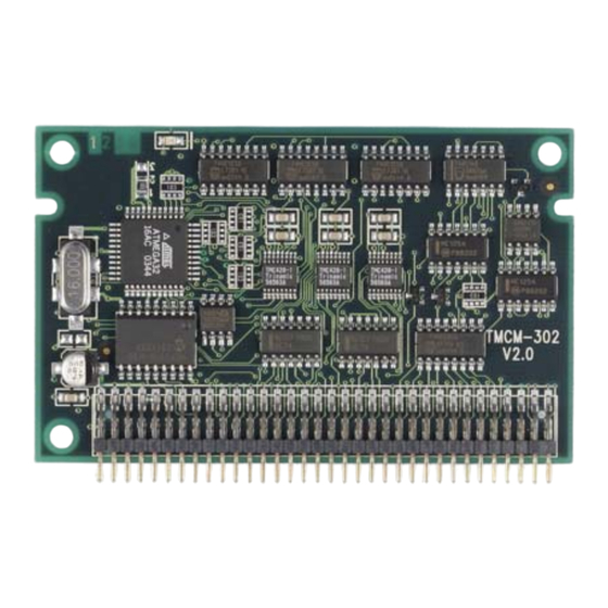
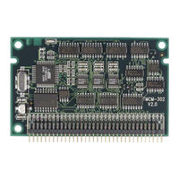
3 - Axis Stepper Motor Motion Control Module for Step / Direction drivers
Brand:
Trinamic
| Category:
Controller
| Size: 0 MB
Table of Contents
Table of Contents
2
1 Features
4
Table 1.1: Order Codes
4
2 Life Support Policy
5
3 Electrical and Mechanical Interfacing
6
Dimensions
6
Figure 3.1: Dimensions
6
Connecting the Module
7
Figure 3.2: Pin Order of the Connector
7
Table 3.1: Pinout 68-Pin Connector
7
4 Operational Ratings
8
5 Functional Description
8
Figure 5.1: Main Parts of the TMCM-302
8
Table 4.1: Operational Ratings
8
Power Supply
9
System Architecture
9
Microcontroller
9
Tmcl Eeprom
9
TMC428 Motion Controller
9
Interface to the External Drivers
9
Table 5.1: Pinning of Power Supply
9
Host Communication
10
CAN 2.0B
10
Figure 5.2: Connecting CAN
10
Table 5.2: Pinout for CAN Connection
10
Table 5.3: Pinout for RS-232 Connection
10
Figure 5.3: Connecting RS-232
11
Figure 5.4: Connecting the RS-485 Interface
11
Table 5.4: Pinout for RS-485 Connection
11
Connecting the Drivers
12
Connecting the TMCM-302 to a Power Driver Module with Step/Direction-Interface
12
Figure 5.5: Step-/Direction Output Signals
12
Table 5.5: Pinout for Using the Step/Direction-Interface
12
Figure 5.6: Application Environment Using the Step/Direction-Interface
13
Figure 5.7: Application with Power Module Monopack 2 with a Step/Direction-Interface
13
Figure 5.8: Application with TMCM-023 with 3 Step/Direction-Interfaces
14
Figure 5.9: Application with TMCM-013 with a Step/Direction-Interface
14
Connecting the TMCM-302 to Drivers with an SPI-Interface
15
Figure 5.10: Application Environment Using the SPI-Interface
15
Table 5.6: Pinout for the Connections Using the SPI-Interface
15
Figure 5.11: Application with an SPI-Stepper Motor Driver
16
Step-/Direction Output
12
Figure 5.12: Velocity Profile in Ramp Mode
17
Figure 5.13: Velocity Profile in Velocity Mode
17
Ramp Profiles
17
Reference Switches
18
Left and Right Limit Switches
18
Triple Switch Configuration
18
Figure 5.14: Left and Right Limit Switches
18
Figure 5.15: Limit Switch and Reference Switch
18
Table 5.7: Pinout Reference Switches
18
One Limit Switch for Circular Systems
19
Figure 5.16: One Reference Switch
19
Port Expansion
19
Serial Peripheral Interface (SPI)
19
Table 5.8: Pinout Serial Peripheral Interface
19
Table 5.9: Pinout Port Expansion
19
Miscellaneous Connections
20
6 Putting the TMCM-302 into Operation
20
Table 5.10: Miscellaneous Connections
20
7 TMCM-302 Operational Description
21
Calculation: Velocity and Acceleration Vs. Microstep- and Fullstep-Frequency
21
Table 7.1: TMC428 Velocity Parameters
21
8 Tmcl
22
9 Revision History
23
Documentation Revision
23
Firmware Revision
23
10 References
23
Table 9.1: Documentation Revisions
23
Table 9.2: Firmware Revisions
23
Advertisement
Advertisement
Related Products
Trinamic TMCM-310
Trinamic TMCM-351
Trinamic TMCM-342
Trinamic TMCM-3110
Trinamic TMCM-1181
Trinamic TMCL-LITE TMCM-1316
Trinamic TMCM-113-60-SE
Trinamic TMCM-078
Trinamic TMCM-1141
Trinamic TMCM-013-42-LA
Trinamic Categories
Controller
Control Unit
Motherboard
Computer Hardware
Engine
More Trinamic Manuals
Login
Sign In
OR
Sign in with Facebook
Sign in with Google
Upload manual
Upload from disk
Upload from URL