Table of Contents
Advertisement
Quick Links
G874 LCD OWNER'S MANUAL CONTENTS
1. INTRODUCTION ............................................................................
2. SAFETY PRECAUTIONS ..............................................................
3. WARNING LABEL POSITION .......................................................
4. LIST OF PARTS ............................................................................
5. ASSEMBLE THE PRODUCT .......................................................... 12
STEP 1 Install the Main Frame .......................................................... 12
STEP 2 Install the Console ...............................................................
STEP 3 Install the Outer Link Pedal Arm Covers ................................. 16
STEP 4 Install the Front Base Cover................................................... 17
STEP 5 Install the Pedals ................................................................... 18
STEP 6 Precautions When Installing the Pedals ................................ 19
STEP 7 Move the Elliptical Trainer in Place ........................................ 20
STEP 8 Level the Product ................................................................... 21
STEP 9 Power Cord Installation Instructions ......................................
STEP 10 Power Supply Protection(Circuit Breaker) ...........................
6. UNDERSTAND THE G874 LCD DISPLAY ......................................
DISPLAY Overview ...........................................................................
DISPLAY Console Panel ...................................................................
DISPLAY Windows Display ................................................................ 25
DISPLAY Specifications ..................................................................... 25
DISPLAY Button Functions ................................................................ 26
7. OPERATE THE PRODUCT ...........................................................
OPERATION Safe Operating Area ...................................................
OPERATION Beware of Moving Parts ...............................................
OPERATION Essential Functions Guide ...........................................
OPERATION Safely Get On/Off ........................................................
OPERATION Proper Workout Position ............................................... 32
OPERATION Start Screen ................................................................
OPERATION User Setting Procedure ...............................................
OPERATION Workout Programs .......................................................
OPERATION During Exercise ...........................................................
OPERATION Cool Down ...................................................................
OPERATION Stop/Pause Exercise ..................................................... 39
OPERATION Workout Summary .......................................................
OPERATION Idle Mode ..................................................................... 40
OPERATION Auto Power Off Function ..............................................
OPERATION User Parameter Setting ...............................................
8. ABOUT HEART RATE DETECTION .............................................
HEART RATE Telemetry ...................................................................
HEART RATE Contact ......................................................................
3
4
8
9
15
22
23
24
24
24
28
28
29
30
31
33
33
36
39
39
39
40
41
43
43
43
Advertisement
Table of Contents

Subscribe to Our Youtube Channel
Related Manuals for SportsArt Fitness G874 LCD


Summary of Contents for SportsArt Fitness G874 LCD
-
Page 1: Table Of Contents
STEP 8 Level the Product ..............21 STEP 9 Power Cord Installation Instructions ........STEP 10 Power Supply Protection(Circuit Breaker) ......6. UNDERSTAND THE G874 LCD DISPLAY ........DISPLAY Overview ................DISPLAY Console Panel ..............DISPLAY Windows Display ..............25 DISPLAY Specifications .............. - Page 2 G874 OWNER’S MANUAL CONTENTS 9. GUIDELINES FOR EXERCISE ............. 10. Micro Inverter MI-250 ..............45 MICRO INVERTER Important Safety Instructions ......45 MICRO INVERTER Cautionary Messages ......... 45 MICRO INVERTER Electronic Specifications ........47 MICRO INVERTER Circuit Board & Product Settings ......48 11.
-
Page 3: Introduction
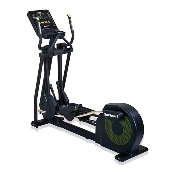
1. INTRODUCTION Congratulations on the purchase of a high quality SportsArt product, the G874 Elliptical trainer. Constructed of high quality materials and designed for years of reliable performance, this product was made for full commercial use. Before this product is assembled or operated, we recommend that you familiarize yourself with this manual. -
Page 4: Safety Precautions
2. SAFETY PRECAUTIONS This product was designed and built for optimum safety. However certain precautions apply during the use of this product. Please note the following safety precautions: ● To reduce the risk of personal injury, read and understand all the instructions before using this product. - Page 5 2. SAFETY PRECAUTIONS (CONT.) ● This product is not intended for use by persons (including children 12 or younger) with reduced physical, sensory, or mental capabilities, or by people who are otherwise deficient in product knowledge or experience. If such people use this product, they should be given training and be supervised at all times by someone responsible for their safety.
- Page 6 2. SAFETY PRECAUTIONS (CONT.) ● This equipment has been tested and found to comply with the limits for a Class B digital device, pursuant to part 15 of the FCC Rules. These limits are designed to provide reasonable protection against harmful interference in a residential installation.
- Page 7 2. SAFETY PRECAUTIONS (CONT.) MARKINGS CAUTION: ● Read instruction manual before using. ● Do not let children on or near the product. WARRING: ● Heart rate monitoring system may be inaccurate. ● Over exercise may result in serious injury or death. ●...
-
Page 8: Warning Label Position
3. WARNING LABEL POSITION If you are in French-speaking areas in North America, display the warning label on console panel as shown below, or in an obvious location that is visible to the user. NOTE: The label is available exclusively in French-speaking areas in North America. -
Page 9: List Of Parts
4. LIST OF PARTS Assembly Parts Name Qty. Name Qty. A1 Main frame Front base cover A2 Stationary handlebar Left support tube A3 Console Right support tube A4 Left/right joint covers A10 Foot pedals A5 Left pedestal cover A11 Pedal bottom covers Outer link pedal arm A6 Right pedestal cover covers... - Page 10 4. LIST OF PARTS (CONTINUED) HARDWARE KIT Name Qty. Specification Notes Inner hex screw M10*P1.5*L20 Toothed lock washer D20*d10.2*t2.0 Secondary roller axle D9.96*L54 self-lubricating bushing Secondary roller Stride adjustment linkage cover Hex nut M10*P1.5 Stopper Ø30-30 Round shaped screw cap Mushroom top philips screw M4*L16 Round shaped screw cap...
- Page 11 4. LIST OF PARTS (CONTINUED) Pre-Installed Hardware Name Specification Notes Hex socket flat head cap screw M10*P1.5*L20 5/16”*L2-1/4” Inner hex screw Half tooth Flat washer D20*d8*t2.0 Mushroom top inner hex screw M8*P1.25*L15 Flat washer D17*d8.3*t2 Inner hex screw M6*P1.0*L15 Handlebar washer D20*d7*t2 Mushroom top inner hex screw M6*P1.0*L15...
-
Page 12: Assemble The Product
5. ASSEMBLE THE PRODUCT STEP 1 Install the Main Frame (1) Remove all packaging material and place the main frame on the carton base. (2) Lift the console mast into upright position, and then tighten the following screws in sequence: screw (33) in (area D), screw (10) in (area A), and screws (10) in (area B,C). - Page 13 STEP 1 Install the Main Frame (Cont.) (5-1) (a) Slip the glide rail into the pedal carriage and lower swing arm. (b) Install the secondary roller (11) to the bottom of glide rail. (NOTE: Insert the axle toward inner side from outer side) (5-2) Insert the axle shaft into housing on the pedal arm, then tighten screw (34) to secure the assembly, and put the stride adjustment linkage cov- er(12) on.
- Page 14 STEP 1 Install the Main Frame (Cont.) (6-1) Insert left and right support tubes (A8)(A9) into the axle area and base, and loosely secure them into place with screws (35) (36) (6-2) Install the stationary handlebar (A2) to the left/right support tube and using screw (37) to secure the assembly.
-
Page 15: Step 2 Install The Console
STEP 2 Install the Console (1) Remove the following parts from the console(A3): anti-slip pad (51), round shaped screw cap(18), screws (52)(53), and bottle holder (54). (2) Secure the console (A3) to the main frame (A1) with pre-installed screw (39). (3) Remove the rear cover (55), and then connect the cables of the main frame (A1) to the cables of the console (A3). -
Page 16: Step 3 Install The Outer Link Pedal Arm Covers
STEP 3 Install the Outer Link Pedal Arm Covers (1) Rotate the pedal arm to the position shown in the figure below, then put on cover B and rotate it 270 degrees clockwise. (2) Snap cover B and cover C together, and rotate the pedal arm until (area A) is easily accessed, then tighten screws (16)(17). -
Page 17: Step 4 Install The Front Base Cover
STEP 4 Install the Front Base Cover Secure left/right pedestal cover(A5)(A6) to the main frame using screw (15), then put on the round shaped screw cap (15) and the front base cover (A7). -
Page 18: Step 5 Install The Pedals
STEP 5 Install the Pedals (1) Secure the pedal bottom cover (A11) to the main frame using screws (40), and then put on the round shaped screw cap (14). (2) Pull up part A, and then secure the foot pedal (A10) onto its mount on the pedal carriage (A1) using screw (41). -
Page 19: Step 6 Precautions When Installing The Pedals
STEP 6 Precautions When Installing the Pedals (1) Make sure the 2 nibs in (area L) are pushed into the holes on the foot pedal. (2) Tighten screws (m1), then push the 2 nibs in (area M) into the holes on the foot pedal. -
Page 20: Step 7 Move The Elliptical Trainer In Place
STEP 7 Move the Elliptical Trainer in Place Grip and lift the main base of the elliptical trainer, and then move it to the desired location. Be careful not to pinch your fingers when you put down the elliptical trainer. -
Page 21: Step 8 Level The Product
STEP 8 Level the Product (1) If your workout area is uneven, or if the rail assembly is slightly off the floor, loosen the locking nut at the back of the equipment and adjust the leveler until it is evenly balanced in contact with the floor, then tighten up the locking screw. -
Page 22: Step 9 Power Cord Installation Instructions
STEP 9 Power Cord Installation Instructions (1) Remove the screw (42) from the base of the main frame. (2) Insert the power cord plug into the connector on the product. (3) Plug the power cord (A13) into the outlet and secure the power cord plug into place with the removed screw (42). -
Page 23: Step 10 Power Supply Protection(Circuit Breaker)
STEP 10 Power Supply Protection(Circuit Breaker) (a) A circuit breaker is an automatically operated electrical switch designed to protect an electrical circuit from damage caused by overcurrent/ overload or short circuit. A spring located under the push button causes the button at area D to lift up and the breaker to trip as shown. (b) After the fault is repaired by qualified technicians, press the push button to reset circuit breaker to resume normal operation as shown. -
Page 24: Understand The G874 Lcd Display
6. UNDERSTAND G874 LCD DISPLAY DISPLAY Overview In this chapter, you will learn how to use and set up the console of your elliptical trainer. Please read the entire manual prior to using the elliptical trainer to get the best exercise efficiency and enjoy your workout. -
Page 25: Display Windows Display
DISPLAY Window Display Description Display the data of your heart rate value. (Displayed when BOTH HANDS hold on the sensor.) Display SPM or current stride length. Display the messages or the illustration. Display the total time covered or the remaining time. Display the cumulative number of Watt-hour To GRID. -
Page 26: Display Button Functions
DISPLAY Button Function Illustration Description The button has two functions: (1) Skip the user input, program selection, and start train- ing instantly. (2) After the parameter settings are complete, press the key to confirm your selection. Press the button to stop/pause your workout progrqm; Hold down to go back to start screen and reset it to fac- tory settings Press this key to change stride length. - Page 27 DISPLAY Button Function (Cont.) Illustration Description Press this key to select one of an almost endless num- ber of randomly generated workout programs. Each key press, the console will randomly generate a different pro- gram. the notification LED will light on steadily. Press this key to enter FIT TEST mode.
-
Page 28: Operate The Product
7. OPERATE THE PRODUCT OPERATION Safe Operating Area (a) Safety clearance required as shown below. Do not allow people to be near this area when operating. (b) Noise emission under load is higher than without load. 600mm(23.6") -
Page 29: Operation Beware Of Moving Parts
OPERATION Beware of Moving Parts This product has moving parts that could be a danger to people and animals. During use, do not put hands or other objects into the stride adjustment slot, the rear cover opening, or other areas in which such action might present a hazard. -
Page 30: Operation Essential Functions Guide
OPERATION Essential Functions Guide LENGTH: Adjust the distance between two successive placements of the same foot. RESISTANCE: Adjust the weight or force you need to place on the pedals to push them. -
Page 31: Operation Safely Get On/Off
OPERATION Safely Get On/Off (a) Place your feet on floor and then hold the handles to steady self while stepping on the pedals as shown below. (b) Wait until pedals come to a complete stop and then hold onto handles for stability while carefully stepping off the elliptical. -
Page 32: Operation Proper Workout Position
OPERATION Proper Workout Position (a) Proper workout position for user is shown below. (b) Over exercising or improper workout form may result in serious injury. (c) User can hold onto handles for stability when getting on or getting off from the right/left side of the elliptical. (d) This product is intended for exercise arms and legs. -
Page 33: Operation Start Screen
OPERATION Start Screen Step on the pedal to start the machine. After started, you will hear the BEEP sound and see the start screen. OPERATION <GO> Mode GO mode is preset based on user 35 years old and weighs 75 kilograms (165 pounds). - Page 34 OPERATION User Setting Procedure (Continued) Parameter Window Description Setting a TIME workout goal: Select <TIME> as your workout goal, the <TIME> notification LED light will stay on and then proceed to time set- tings. The range is 5 - 300 minutes with the default of 30 minutes.
- Page 35 OPERATION User Setting Procedure (Continued) Parameter Window Description Setting a Watt-hour TO GRID work- out goal: Select < Watt-hour TO GRID > as your workout goal, the < Watt-hour TO GRID > notification LED light will stay on and then proceed to Watt-hour TO GRID settings.
-
Page 36: Operation Workout Programs
OPERATION Workout Programs You can choose the desired program from the PROGRAM menu. The following information provide details about the programs. MANUAL: The general mode. Users can set their desired workout program.The resistance and stride length can be adjusted according to your own preference. - Page 37 OPERATION Workout Programs (Continued) RANDOM: The graphic pattern in RANDOM PROGRAM are generated randomly, and the illustration shows differently each time (1) Press the <RANDOM> key to select the desired graphic pattern. (2) During exercise, you can press the <RANDOM> key to change the graphic pattern.
- Page 38 OPERATION Workout Programs (Continued) WT LOSS , CARDIO: The programs take control of resistance, keeping your heart rate within the target zone. (1) Before entering this mode, press <WT LOSS/CARDIO> key to toggle between WT LOSS and CARDIO. The words “♥ 120” shown on the display represent WT LOSS mode, and the words “♥...
-
Page 39: Operation During Exercise
OPERATION During Exercise During exercise, you can switch to a different program using the same WORKOUT GOAL(TIME/DISTANCE/CALORIES/Watt-hour TO GRID) by pressing a different program key. Please note it is not allowed to switch directly in the situation as below, and the window will display the message ”... -
Page 40: Operation Idle Mode
OPERATION Idle Mode The machine will turn into power saving mode when there is no stepping on the pedal or not been operated to the buttons for 50 seconds, and the window will display “- - - -“ and continue to flash. To restart the machine, please step on the pedal or press any button to return to start screen. -
Page 41: Operation User Parameter Setting
OPERATION User Parameter Setting Hold the <RESISTANCE - > for 3 seconds to enter the user parameter setting procedures; press the <STOP> key at any time to return to the start screen. Please refer to the following setting procedures: (1) Metric System / Imperial Units Setting The window will display KM or MILE, press <LENGTH ▲/▼>... - Page 42 OPERATION User Parameter Setting (Continued) (6) Product Serial Number The Window will show the message of “S/N xxxxxxxx” (as shown below), press <GO/ENTER > and go to the next step. ※ The number “1234567” in the picture represents the machine serial number.
-
Page 43: About Heart Rate Detection
8. ABOUT HEART RATE DETECTION Heart rate detection functions are selected at the time of purchase. Not every product has every type of heart rate detection. The following explains factors that influence the performance of two of the most common types of heart rate detection devices. -
Page 44: Guidelines For Exercise
9. GUIDELINES FOR EXERCISE HOW HARD SHOULD I EXERCISE? Studies show that to benefit from aerobic exercise, people need to maintain a certain heart rate during their workouts. Your heart rate training zone depends on your age and fitness level. The darkened area in the chart to the right represents the recommended heart rate training zone for people of various ages. -
Page 45: Micro Inverter Mi-250
10. MICRO INVERTER MI-250 MICRO INVERTER Important Safety Instructions CAUTION These servicing instructions are for use by qualified personnel only. To re- duce the risk of electric shock, do not perform any servicing other than that specified in the operating instructions unless you are qualified to do so. PRUDENCE! Ces instructions d’entretien sont uniquement destinées à... - Page 46 MICRO INVERTER Cautionary Messages (Continued) WARNING Power fed from more than one source. Each circuit must be individually disconnected before servicing. Do not remove cover until 5 minute after disconnecting all sources of supply. AVERTISSEMENT! L’alimentation provient de plus d’une śource. Chaque circuit doit étre coupé avant toute intervention de dépannage.
-
Page 47: Micro Inverter Electronic Specifications
MICRO INVERTER Electronic Specifications Input Data(3 Phase AC) Input power source 3 Phase permanent-magnet generator Maximum input voltage 140V(line-to-line voltage) Nominal operating voltage range 55-125V(line-to-line voltage) Maximum input current 7A(line current) Output Data(single phase AC) Maximum continuous output power 220W Output power factor rating >0.9 120VAC(105.6-132.0V) (for USA) -
Page 48: Micro Inverter Circuit Board & Product Settings
MICRO INVERTER Circuit Board & Product Settings Frequency setting: MI-250 can detect the frequency automatically without setting. Connecting to grid power: After MI-250 is installed into Eco-Powr products, the power can be linked to grid power through product power cord, as shown in the following figure. At- tention: it is necessary to cover the power cord and product connecting area with a metal cover. - Page 49 MICRO INVERTER Circuit Board & Product Settings (Cont.) This optional accessory SportsArt Eco-Powr Daisy Chain unit connection cord is suitable SportsArt Eco-Powr Daisy Chain cable unit connection cable allows multiple Eco-Powr products to be powered from a single electrical socket. SportsArt Eco-Powr Products 4th...
-
Page 50: Maintenance
11. MAINTENANCE Maintenance topics are presented below in the following order: error mes- sages, lubrication of the shoulder area, lubrication of the stride area, glide rail cleaning, maintenance schedule, task list, one-year maintenance log, and electronics block diagram. MAINTENANCE Safety Precautions ●... -
Page 51: Maintenance Error Messages
MAINTENANCE Error Messages The window will show the error message when an unusual situation occurs on the machine. (Shown as illustration below, X is for the main code, Y is for the secondary code.) Error Code Description: Main Secondary Error message Note Code X Code Y... - Page 52 MAINTENANCE Error Messages (Continued) Main Secondary Error message Note Code X Code Y AC grounded failure. DC_BUS`s tension is overloaded. Forced to warm up. Forced to EngStop Generator`s current is overloaded. Generator is failure in voltage Generator`s temperature is too high.
-
Page 53: Maintenance Messages
MAINTENANCE Messages SERVICE BATTERY The flashing light signals battery is near depletion (this signal appears when adjusting stride length, with a pedal speed less than 30 SPM),please charge the battery in one of the following ways: a. Charge the battery by pedaling. b. -
Page 54: Maintenance Lubrication Procedure
MAINTENANCE Lubrication Procedure (a) Push in at point A, and slide upward to remove the lubrication cover. (b) Press the stride up key to adjust the stride to its longest point. Note the grease fitting at area B. (c) Use an automobile grease gun with red lithium grease. Apply the grease to the nozzle on the product. -
Page 55: Maintenance Cleaning The Glide Rails
MAINTENANCE Cleaning the Glide Rails Follow the steps below to clean left and right glide rails on a daily basis: (a) Use a clean, lint-free cloth to wipe dust and debris off the glide rails. (b) Test the glide rails to ensure they move easily and smoothly. (c) Repeat steps (a) and (b) two or three times to ensure smooth movement. -
Page 56: Maintenance Schedule
MAINTENANCE Schedule If there is a need for maintenance of components, please visit the SportsArt website. cleaning requirements 1.directive 93/42/CEE 2.directive biocide 98/8/CEE The disinfectant has to be in compliance with Medical Device Directive 93/42/EEC (MDD) and Biocidal Products Directive 98/8/EC (BPD). It is suited for sensitive synthetic surfaces such as synthetic leather, poly- carbonate (PC), acrylic glass and polysulfone, and for the keyboards and control panels. -
Page 57: Accessories
12. ACCESSORIES ACCESSORIES Standard USB PORT 1. Provides up to 5V, 0.5A of power for charging 2. Let you update all required software drivers for the product. CSAFE PORT Compatible with CSAFE (Communications Specification for Fitness Equip ment) Protocol. *The figure below is for reference purposes only. QR code and NFC tag 1. -
Page 58: Accessories Option
ACCESSORIES Option SA WELL+ Member System This is designed specially by SportsArt to assist the user in managing their workout history. There are three ways to get connected with the member site: 1. Using a smartphone, connect to the unit via Bluetooth/WIFI and use the SA WELL+ App. - Page 59 ACCESSORIES Option (Continued) TV Mount Bracket...
-
Page 60: Appendixes
13. APPENDIXES APPENDIX Specifications Model G874 L : 2085 mm (82”) Dimensions W : 680 mm (26.8”) H : 1765 mm (69.5”) Overall Weight 146kg (322 lbs) Maximum User 205 kg (450 lbs) Weight 100 - 120 V , 60Hz , 2.2A (USA) Power Requirement 200 - 240 V , 50Hz , 1.1A (EUROPE) Circuit Breaker... -
Page 61: Appendixes Electronics Block Diagram
APPENDIX Electronics Block Diagram HTR Board T674 V886 SA WELL SA WELL+ Key Board Key Board Option Connection key SA WELL Board Control Board USB Board USB Board HRC Board LENGTH(Left) RESISTANCE(Right) Stepper Motor Contact HTR plates INCL Board 組 MI Drive Board AVB NET2 Board 組... -
Page 62: Appendixes Exploded Diagrams
APPENDIX Exploded Diagrams Note: We reserve the right to revise the following diagrams at any time without notice to notify any person of such revisions. Please visit our official website www.gosportsart.com for the latest version. -
Page 63: Appendixes Disassembly
APPENDIX Disassembly (a) Main Frame (b) Lift Motor Assembly (c) Front Base Cover... - Page 64 SPORTS ART INDUSTRIAL CO., LTD. NORTH & LATIN AMERICA (Headquarters) 8217 44th Ave W. Suite A, No. 11, Gong Huan Road, Tainan City, Mukilteo WA 98275, 70955 Taiwan TEL: +886 6 3840 888 TEL: +1 425 4819479 FAX: +886 6 3840 999 FAX: +1 425 4888155 E-mail: info@sportsart.com.tw E-mail: info@gosportsart.com...
Need help?
Do you have a question about the G874 LCD and is the answer not in the manual?
Questions and answers