Table of Contents
Advertisement
Advertisement
Table of Contents

Related Manuals for SportsArt Fitness XT20 Fitness


Summary of Contents for SportsArt Fitness XT20 Fitness
- Page 1 XT20...
-
Page 2: Table Of Contents
SPORTS ART COMMERCIAL GRADE XT20 X-TRAINER TABLE OF CONTENTS A. SAFETY GUIDELINES ..................B. INTRODUCTION....................C. ASSEMBLING YOUR X-TRAINER List of parts......................Step by step instructions..................D. UNDERSTANDING THE XT20 DISPLAY CONSOLE Windows....................... Keypad......................... E. OPERATING YOUR X-TRAINER Power Up the X-Trainer.................. -
Page 3: Safety Guidelines
A. SAFETY GUIDELINES: Please read and follow the following safety guidelines: Keep this owner's manual for future use and reference. Read this owner's manual and follow the instructions. Assemble and operate the SportsArt XT20 Trainer on a solid, level surface. Never allow children on or near the machine. -
Page 4: Introduction
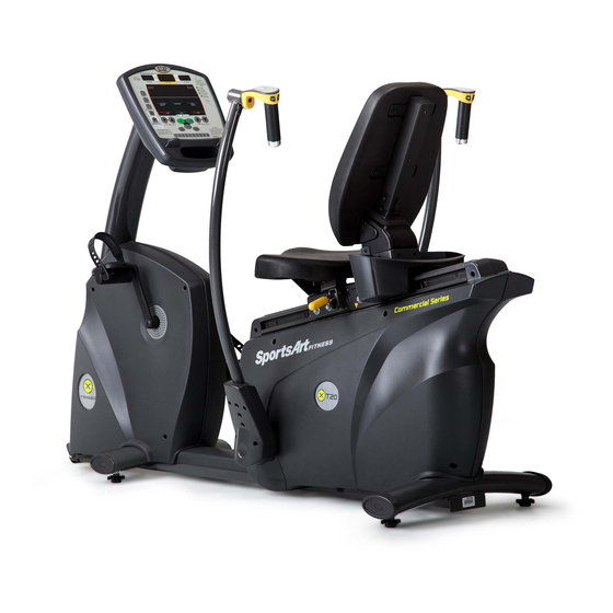
B. INTRODUCTION Congratulations on purchasing one of the finest pieces of commercial grade exercise equipment in the market today, the SportsArt XT20. Constructed of high quality materials and designed for years of trouble free usage, the XT20 will be an integral part of your fitness regimen. -
Page 5: Assembling Your X-Trainer
C. ASSEMBLING YOUR X-TRAINER LIST OF PARTS: 1. One Display Support Tube 2. One Left Pedal 3. One Right Pedal 4. One Seat Back 5. One Seat Bottom 6. One Left Upper Body Bar 7. One Right Upper Body Bar 8. -
Page 6: Step By Step Instructions
STEP BY STEP INSTRUCTIONS Before assembling your X-trainer, make sure that you have all parts listed on the previous page. Refer to the product illustration below. Product Illustration Electronics Package Leg Resistance Switch Electronics Display Pedestal Upper Body Handle Handlebar end cap Magazine Tray Arm Resistance Switch Pedal... - Page 7 The following steps explain how to assemble your SportsArt XT20. Please read every step thoroughly. Follow the directions completely to ensure correct assembly. 1. Remove the trainer from the box and separate packing material from the trainer parts. 2. Place all parts on a flat surface so that they can be found more easily. 3.
- Page 8 4. Install right and left Pedals to right and left crank arms respectively, using the wrench provided. Be careful to distinguish L from Left is the user's left, as he or she exercises on the equipment. After installation, rotate pedals counterclockwise to secure them (see the following illustration).
- Page 9 6. Insert right and left upper body bars into their respective connector tubes. Secure the bars with the four bolts attached. Connect the wires in the upper body bars. Attach the exterior enclosure firstly that two ribs on it go into the holes on the bottom of upper body bars as step , then put the interior enclosure in placement as step...
- Page 10 7. Floor Level Adjustment If the trainer is unsteady on the floor, turn the levelers on the front and rear feet. Raise or lower the levelers to steady your trainer on the floor. Secure the adjustment level with the washers attached, as illustrated below: 8.
- Page 11 9. The marking on the seat rail is there to assist the user to record his or her favorite position (as shown in the following illustration). The XT20 Trainer is now assembled and ready for use.
-
Page 12: Understanding The Xt20 Display Console
D. UNDERSTANDING THE XT20 DISPLAY CONSOLE: The SportsArt XT20 display console provides user-friendly control of all X-trainer functions. OVERVIEW OF THE DISPLAY CONSOLE WINDOWS a. 65% HR Target. The weight loss program adjusts resistance to keep the user's heart rate at 65% of the maximum heart rate. This provides the optimum weight loss workout. -
Page 13: Keypad
c. 80% HR Target. The cardio training program adjusts resistance to keep the user's heart rate at 80% of the maximum heart rate. This provides the optimum cardio training workout. d. DOT MATRIX WINDOW shows operating instructions and workout feedback. e. - Page 14 l. STOP/RESET. In any preset exercise program, press this button to end that program. When this button is pressed, the dot matrix panel will show STOP for 3 seconds and beep for 0.5 second. TOTAL TIME + AVERAGE HR will appear.
-
Page 15: Operating Your X-Trainer
E. OPERATING YOUR X-TRAINER a. POWER UP THE X-TRAINER Either press the <START> button, start pedaling, or start moving the arm conditioner bars to activate the unit. "XT20" will appear on the dot matrix window. No other messages will be shown on other windows at this time. b. -
Page 16: Entering User's Personal Information
NOTES: 1. The blinking dot moves only when you pedal. It does not move if you only exercise your arms. 2. The distance exercised per dot cycle is 0.25 mile or 0.4 km. b-5. While exercising, press < > < > buttons to change pedal or arm resistance. The values shown for LEG WORK LEVEL &... -
Page 17: Power Standby Mode
If the weight entry exceeds the weight range, "WRONG NUMBER" will scroll across the display. (Weight values can range from 20 to 150 kgs or from 50 to 330 lbs.) c-3. Setting the Program After the weight is set, "SELECT PROGRAM" scrolls across the dot matrix window. -
Page 18: Overview Of Programs
F. OVERVIEW OF PROGRAMS a. MANUAL a-1. The first time you enter the Manual Mode, both upper body resistance and lower body resistance are preset at LEVEL 1. a-2. Press the MANUAL button to enter Manual Mode. This is the default setting. Once the manual mode program is selected, the dot matrix window displays the following pattern (see Pattern 3), which is similar to the pattern seen in Quick Start Mode. -
Page 19: Random
b. RANDOM b-1. The first time you enter the Random Mode, the arm resistance is preset at LEVEL 3 and the pedal resistance is preset at LEVEL 5. In this mode, the workout always starts from column 10, as shown in the following illustration. Leg Resistance Arm Resistance Level... -
Page 20: Wt Loss (Hrc 65%) / Cardio (Hrc 80%)
b-4. The workout illustration moves one column to the left every 10 seconds. The dot at the current location blinks only when you pedal or exercise your arms. The dot will be lit constantly if no action is taken. b-5. Time starts to count down in the TIME window. The program begins the COOL DOWN procedure when the time is 0 (zero). -
Page 21: Conditioning And Advanced Conditioning
c-4. It is not necessary to reset the target heart rate if you switch from a weight loss to a cardio conditioning program. Simply press WT Loss/CARDIO, then press <ENTER> to confirm your choice. c-5. At the beginning of the cardio conditioning program, the preset arm resistance level is 3, and the preset pedal resistance level is 5. - Page 22 d. CONDITIONING and ADVANCED CONDITIONING d-1. CONDITIONING and ADVANCED CONDITIONING programs each contain four preset workout programs. Please refer to the following illustration. Starting point of CONDITIONING: press button once press button twice press button three times press button four times TONING 20 TONING 30 STRENGTH 20...
-
Page 23: Cool Down
d-5. The time bar is located at the bottom of the dot matrix window. Every dot stands for <total workout time/25>. d-6. In the time window, the time starts to count down, and the COOL DOWN procedure begins when the countdown reaches zero. d-7. -
Page 24: Displaying Workout Data
g. Displaying Workout Data To display workout data, press the <STOP/RESET> button any time during a workout. The dot matrix window shows the prompt "STOP". The display shows workout data as follows: HEART RATE average heart rate DOT MATRIX "XT20" SPEED/DISTANCE total workout distance CALORIES/CAL HR... -
Page 25: System Default Setting
G. SYSTEM DEFAULT SETTING In the initial screen, where the display shows "XT20", press LEG Work LEVEL < > + < > simultaneously for more than one second to enter the system default setting. Please refer to the following procedure to determine default settings. a. -
Page 26: Setting Ranges
Weight: 20 ~150 KG or 50 ~ 330 LB Age: 10~99 J. MAINTAINING THE TRAINER XT20 The Sports Art XT20 requires little maintenance. But smooth operation does require some cleaning. Regular cleaning is recommended to keep your trainer XT20 at peak performance. -
Page 27: Troubleshooting
(+) and it with screws. negative end (-) according to the indications). Press the battery bottom cap back. 2. If the unit still does not function properly after replacing the batteries, please contact your authorized Sports Art dealer. -
Page 28: Appendix: Wiring Schematic
Appendix: Wiring Schematic: Note: the specification of Battery Charger is DC 16~20V/2A. The Battery Charger is not shipped along with the trainer. Please buy the Battery Charger directly from your market.
Need help?
Do you have a question about the XT20 Fitness and is the answer not in the manual?
Questions and answers