
Related Manuals for SportsArt Fitness G862


Summary of Contents for SportsArt Fitness G862
- Page 1 G862 Elliptical Trainer Owner’s Manual Sports Art Industrial Co., Ltd. TUV-CERT ISO 9001/9002/14000 Certified Quality Products 2012.07.22...
-
Page 2: Table Of Contents
STEP 12 Establish the Number of Units per Pod ........ STEP 13 Install the CES, if Desired ............ STEP 14 Avoid Safety Hazards ............5. UNDERSTAND THE G862 DISPLAY ..........20 DISPLAY Overview ................DISPLAY Specifications ............... DISPLAY Windows ................21 DISPLAY Keys .................. -
Page 3: Introduction
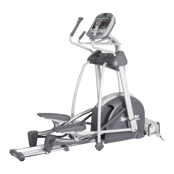
Congratulations on your purchase of one of the finest exercise products on the market today, the SportsArt G862 elliptical trainer. Constructed of high quality materials and designed for years of reliable usage, this product was made to become an integral part of your commercial fitness venue. -
Page 4: Safety Precautions
2. SAFETY PRECAUTIONS This product was designed and built for optimum safety. However certain precau- tions apply during the use of this product. Please note the following safety precautions: • Please read the entire manual before assembly and operation. Make sure the product is installed and operated as instructed in this manual. - Page 5 2. SAFETY PRECAUTIONS (CONTINUED) Note: This equipment has been tested and found to comply with the limits for a Class B digital device, pursuant to part 15 of the FCC Rules. These limits are designed to provide reasonable protection against harmful interference in a residential instal- lation.
-
Page 6: List Of Parts
3. LIST OF PARTS Assembly Parts Qty. No. Qty. Name Name Main body Right footplate assembly 1 A1A Rail base cover Right base cover Small cover Left base cover Upper cover A10 Hardware kit Right support A11 Boost converter Boost converter Left support connector cable Left footplate assembly 1... - Page 7 Components in the Hardware Kit Name Qty. Specification Notes Mushroom top Phillips screw M4*L16 Inner hex head screw M8*L20 Spring washer D18*d8.5*t2.0*19T Serrated washer Gasket D13*0.25 Left/right adjustment rod cover Screw insert M10 nut cap Screw cap L-shaped Allen wrench L-shaped Allen wrench Double open-end wrench 8*17...
-
Page 8: Assemble The Product
4. ASSEMBLE THE PRODUCT Follow instructions below to assemble this product. Note that in this manual the words “left” and “right” are used to refer to the product and its parts. As such, these designations correspond to the “left” and “right” sides of a person in position to exercise on this product. -
Page 9: Step 2 Assemble The Pedestal
STEP 2 Assemble the Pedestal Please follow instructions (a) through (b) to assemble the pedestal. (a) First, lift the pedestal upright. Be careful to avoid pinching the data cable. (b) Secure screws (34), first in area A, then in area B. -
Page 10: Step 3 Install The Upper Cover
STEP 3 Install the Upper Cover Please follow instructions (a) through (d) to install the upper cover. (a) Slide the water guard pedestal. (This ring must placed above the upper cover.) (b) Install the upper cover and secure it with screw (33). Install small cover (A2) and secure it with... -
Page 11: Step 5 Install Left/Right Supports
STEP 4 Install Linkages/Carriages (Continued) (e) Insert the front of the footplate carriage into the vertical arm. Align it with the hole and use bolt (46) to secure it into place. Then insert caps (37, 38) into place. (f). Lubricate the area where the rod contacts the bushing, hold the footplate carriage into place, and secure it with screw (47). -
Page 12: Step 6 Secure The Rail Base Cover
STEP 5 Install Left/Right Supports (Continued) (e) First, remove screws (41) from the lower part of the supports. Snap covers (A4, A5) into place on the left and right supports (A8, A9). Then secure screws (41). (f) Set upper covers into place on both supports, and secure them with screws (42). -
Page 13: Step 7 Move The Unit Into Place
STEP 7 Move the Unit into Place Follow steps (a) through (c) to move the unit into place for use. (a) Stand behind the unit. Grasp the glide track rods as shown. (b) Lift up. (To avoid injury, always use proper lifting techniques.) (c) Push while using the transport wheels to roll the unit into place. -
Page 14: Step 8 Level The Unit
STEP 8 Level the Unit If the unit does not rest flat on the floor, please follow steps (a) through (b) to level it. (a) Under the front of the unit, rotate the leveler nut upward to enable adjustment of the leveler foot. Then screw the leveler foot downward until it touches the floor. -
Page 15: Step 9 Understand The Green System
STEP 9 Understand the Green System The G862 elliptical trainer is designed for use in a power production system called the Green System. For more information about this system, please refer to the inverter and boost converter installation manuals. Instructions below pertain to installation of the boost converter. -
Page 16: Step 10 Install The Boost Converter
Install the Boost Converter Please follow instructions (a) through (c) to connect the boost converter to G862 elliptical trainer. (a) First, remove screws (48) from the front of the unit (A1). (b) Connect cords from the boost converter (A11) into connectors (A) and (B) on the product. -
Page 17: Step 11 Connect Boost Converters
STEP 11 Connect Boost Converters Before assembling components, make sure that the power supplies on the fitness products and the boost converters are in the off position. First, remove the protective cover from the boost converter (A11). Insert the boost converter connector cord (A12), and secure it into place. -
Page 18: Step 12 Establish The Number Of Units Per Pod
STEP 12 Establish the Number of Products per Pod Upon setup, the number of fitness products per pod must be entered into the memory of each product. If this is not done properly, the inverter might get overloaded and its fuse might break. The procedure to establish the number of fitness products per pod is explained below. -
Page 19: Step 13 Install The Ces, If Desired
STEP 13 Install the CES, if Desired The G862 elliptical trainer can operate with the CardioActive™ Entertainment System, an integrated TV module. If desired, install the integrated TV module after the elliptical trainer is fully assembled. For more information, please... -
Page 20: Step 14 Avoid Safety Hazards
STEP 14 Avoid Safety Hazards While the product is in use, or during maintenance or repair work, be careful to avoid getting pinched by or wedged against moving parts. In particular, do not insert fingers or other body parts into the stride adjustment area or the opening in the front covers. -
Page 21: Understand The G862 Display
5. UNDERSTAND THE G862 DISPLAY DISPLAY Overview The G862 elliptical trainer is designed for user convenience. With better feedback about your workout, you get better results. The following explains the display key and window functions. Please read this manual, understand the display functions, and thereby get optimum enjoyment and benefit from this product. -
Page 22: Display Specifications
DISPLAY Specifications ● Workout level (resistance level): 1 - 20 ● Time: 0:00 - 99:00 ● Distance: 0.01 - 9999 km or mile ● Calories: 0.0 - 9999 kcal ● Calories per hour: 0.0 - 9999 kcal ● Programs: MANUAL, RANDOM, VARI-STRIDE, CARDIO/WT LOSS, INTV, PLATEAU, FAT BURN, CUSTOM HR ●... - Page 23 DISPLAY Keys (Continued) 0 – 9 numeric keys – Press these keys to directly input numbers, rather than pressing ▲/▼ keys. Decimal key – Press this key to insert a decimal point into setting values. ▲/▼ keys – Press these keys to adjust settings up or down. Hold these keys to change settings more quickly.
-
Page 24: Operate The Product
DISPLAY Keys (Continued) STOP/PAUSE/HOLD TO RESET – In Workout mode, press <STOP/PAUSE/ HOLD TO RESET> key to pause the program. The data display will show messages “PAUSED” and “PRESS START TO RESUME”. All the workout data will stop accumulating and remain at the current values. If no operations in 5 minutes, the console will reset and return to BANNER screen. -
Page 25: Operation Cool Down
OPERATION Start a Workout Program (Continued) ● The TIME setting range is from 5:00 to 99:00, with a default value of 30:00. Use ▲/▼ keys or numeric keys (0-9) to make your selection. Press the ENTER key to confirm your setting and proceed to input your age. The DISTANCE setting range is from 0.1 to 99.99 miles or kilometers, with a default value 2.0 miles (3.0 kilometers). - Page 26 OPERATION Workout Programs (Continued) The following explains features of the workout programs. MANUAL This program allows you to manually control resistance. In manual mode, simply press LEVEL ▲/▼ keys to control resistance. RANDOM This program provides a near infinite number of randomly generated workouts. A new workout illustration appears each time the RANDOM key is pressed.
- Page 27 OPERATION Workout Programs (Continued) Interval 1:1 indicates one segment of one minute in duration, followed by a second segment of one minute in duration. Interval 1:2 indicates one segment of one minute in duration, followed by a second segment of two minutes in duration. Interval 2:2 indicates one segment of two minutes in duration, followed by a second segment of two minutes in duration.
-
Page 28: Operation User Preferences And Component Versions
OPERATION Workout Programs (Continued) CUSTOM A heart rate control program, CUSTOM allows you to determine your target heart rate. The CUSTOM heart rate setting range is 84 to 199 beats per minute, with a default setting of 120 beats per minute. Upon entering this workout, “ENTER TARGET HR”... -
Page 29: About Heart Rate Detection
7. ABOUT HEART RATE DETECTION Heart rate detection functions are selected at the time of purchase. Not every product has every type of heart rate detection. The following explains factors that influence the performance of two of the most common types of heart rate detection devices. -
Page 30: Guidelines For Exercise
CAUTION: Heart rate detection and transmission devices have been known to interfere with the operation of pacemakers, possibly endangering human life. If you have a pacemaker, exercise under your doctor’s supervision; take a test to ensure your safety during the simultaneous use of the pacemaker and heart rate detection devices. -
Page 31: Maintenance
9. MAINTENANCE Maintenance topics are presented below in the following order: error messages, lubrication of the shoulder area, lubrication of the stride area, glide rail cleaning, maintenance schedule, task list, one-year maintenance log, and electronics block diagram. MAINTENANCE Error Messages The following messages can appear on this product for diagnostic purposes. -
Page 32: Maintenance Lubricate The Stride Mechanism
MAINTENANCE Lubricate the Shoulder Area (Continued) MAINTENANCE Lubricate the Stride Mechanism Follow steps (a) through (d) to lubricate the stride adjustment mechanism. (a) First, remove the stride access cover: Press at location A, push upward (1), then pull the cover off (2). (b) Adjust the stride to the longest position. -
Page 33: Maintenance Clean The Glide Rail
MAINTENANCE Clean the Glide Rail Clean the glide rails once a day as follows: (a) Use a clean, lint-free cloth to wipe dust and debris off the glide rails. (b) Operate the product to inspect it and to determine where dirt might remain on the glide rails. -
Page 34: Maintenance Schedule
MAINTENANCE Schedule Area Week Month Quarter Year Notes Exterior Clean Screws Inspect and secure loose parts Glide Wipe away dirt rail and debris. Rollers Apply silicone lubricant. Stride Apply grease. motor... -
Page 35: Maintenance Task List (Elliptical Trainers)
MAINTENANCE Task List (Elliptical Trainers) Like cars, fitness products require maintenance. Regular maintenance extends product life, and failure to maintain products can void the manufacturer’s warranty. Copy the maintenance log sheet, and record maintenance work for each fitness product. Daily tasks 1. -
Page 36: Maintenance One-Year Maintenance Log
MAINTENANCE One-Year Maintenance Log Facility:_______________________ Supervisor:____________________ Product model number:__________ Serial number:_________________ Start date: ____________________ End date:_____________________ Daily Tasks Weeks 1-7 Weeks 8-14 Weeks 15-21 Week 22-28 Completed Daily Tasks Week 29-35 Week 36-42 Week 43-49 Week 50-52 Completed Weekly Tasks Weeks 1-7 Weeks 8-14 Weeks 15-21 Weeks 22-28... -
Page 37: Maintenance Boost Converter Disconnection
MAINTENANCE Boost Converter Disconnection If it becomes necessary to detach the boost converter from the fitness product (for example, if the boost converter malfunctions), follow instructions below to disconnect the boost converter. First, turn off the power supply. Then follow sequence (A), (B), (C), (D) to disconnect the boost converter. - Page 38 MAINTENANCE Boost Converter Disconnection (Cont.) Note: Before installing components, make sure that the inverter power switch is in the off position. Push the mode selector switch on the boost converter to the left side. Remove the protective cover from the side of the boost converter. Connect the inverter’s DC cord to the boost converter in front of the first product in the series, and secure the connector with screws.
-
Page 39: Maintenance Electronics Block Diagram
MAINTENANCE Electronics Block Diagram CON8 CON6 CON1 Alternator CON4 KEY PAD C572 CTL Board USB Board HTR Board CON9 CON2 CON7 CON5 HRC Board 板 Stride length & Workout Level Switch :Connector :Converge Speed Sensor HandTouch G872 DRV Board Power plate Stride length Adjustment Motor Power plate - front... -
Page 40: Safety Precautions In French
10. SAFETY PRECAUTIONS IN FRENCH CONSIGNES DE SÉCURITÉ IMPORTANTES ● Votre vélo SportsArt a été conçu et fabriqué afin d’assurer une sécurité optimale. Cependant certaines précautions s’appliquent chaque fois que vous utilisez votre vélo de course. ● Lisez entièrement le manuel avant l’assemblage et l’utilisation. Veuillez aussi noter les consignes de sécurité... - Page 41 ● NE PAS transporter le vélo de course par le cordon d’alimentation et n’utilisez pas le cordon comme poignée. ● Maintenez le cordon éloigné de toute surface chaude. ● Débranchez l’appareil de la prise avant l’entretien ou la suppression de toute pièce.
Need help?
Do you have a question about the G862 and is the answer not in the manual?
Questions and answers