Table of Contents
Advertisement
Quick Links
G876 OWNER'S MANUAL CONTENTS
1. INTRODUCTION ............................................................................
2. SAFETY PRECAUTIONS ..............................................................
3. WARNING LABLE POSITION .......................................................
4. LIST OF PARTS ............................................................................
5. ASSEMBLE THE PRODUCT ..........................................................
STEP 1 Install the Main Frame ..........................................................
STEP 2 Install the Moving Parts ........................................................
STEP 3 Install the Support Tubes ....................................................... 12
STEP 4 Install the Stationary Handlebar .............................................. 13
STEP 5 Install the Console ..............................................................
STEP 6 Install the Pedals ..................................................................
STEP 7 Install the Pedestal Covers .................................................... 16
STEP 8 Move the Product into Place .................................................. 17
STEP 9 Level the Product ................................................................... 18
STEP 10 Power Cord Assembly ......................................................... 19
STEP 11 Beware of Moving Parts ...................................................... 20
STEP 12 Essential Functions Guide .................................................
STEP 13 Power Supply Protection(Circuit Breaker) ............................ 22
6. UNDERSTAND THE G876 DISPLAY ............................................
DISPLAY Overview ...........................................................................
DISPLAY Console Panel ...................................................................
DISPLAY Windows Display ................................................................ 25
DISPLAY Specifications ..................................................................... 26
7. OPERATE THE PRODUCT ...........................................................
OPERATION Safe Operating Area ...................................................
OPERATION Safely Get On/Off ........................................................
OPERATION Proper Workout Position ............................................... 29
OPERATION Start Screen ................................................................
OPERATION Quick Start ...................................................................
OPERATION User Setting Procedure ...............................................
OPERATION Workout Programs .......................................................
OPERATION During Exercise ...........................................................
OPERATION Cool Down ...................................................................
OPERATION Stop and Pause Exercise .............................................. 35
OPERATION Workout Summary .......................................................
OPERATION Idle Mode ..................................................................... 36
OPERATION Energy Smart Function ................................................
OPERATION User Parameter Setting ...............................................
8. ABOUT HEART RATE DETECTION .............................................
HEART RATE Telemetry ...................................................................
HEART RATE Contact ......................................................................
3
4
6
7
9
9
10
14
15
21
23
23
23
27
27
28
30
30
30
32
34
35
35
36
37
39
39
39
Advertisement
Table of Contents

Subscribe to Our Youtube Channel
Related Manuals for SportsArt Fitness G876


Summary of Contents for SportsArt Fitness G876
-
Page 1: Table Of Contents
STEP 11 Beware of Moving Parts ............20 STEP 12 Essential Functions Guide ..........STEP 13 Power Supply Protection(Circuit Breaker) ......22 6. UNDERSTAND THE G876 DISPLAY ..........DISPLAY Overview ................DISPLAY Console Panel ..............DISPLAY Windows Display ..............25 DISPLAY Specifications .............. - Page 2 G876 OWNER’S MANUAL CONTENTS 9. GUIDELINES FOR EXERCISE ............. 10. Micro Inverter MI-250 ..............41 MICRO INVERTER Important Safety Instructions ......41 MICRO INVERTER Cautionary Messages ......... 41 MICRO INVERTER Electronic Specifications ........42 MICRO INVERTER Circuit Board & Product Settings ......43 11.
-
Page 3: Introduction
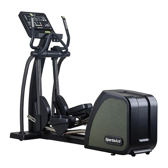
1. INTRODUCTION Congratulations on the purchase of a high quality SportsArt product, the G876 Elliptical trainer. Constructed of high quality materials and designed for years of reliable performance, this product was made for full commercial use. Before this product is assembled or operated, we recommend that you familiarize yourself with this manual. -
Page 4: Safety Precautions
2. SAFETY PRECAUTIONS Your SportsArt elliptical trainer was designed and built for optimum safety. However certain precautions apply whenever you use your elliptical trainer. Please read the entire manual before assembly and operation. Also, please note the following safety precautions: ●... - Page 5 2. SAFETY PRECAUTIONS (CONTINUED) ● This elliptical trainer is not intended for use by persons (including children 12 or younger) with reduced physical, sensory or mental capabilities, or lack of experience and knowledge, unless they have been given supervision or instruction concerning use of this elliptical trainer by a person responsible for their safety.
-
Page 6: Warning Lable Position
3. WARNING LABLE POSITION If you are in a Non-English speaking country, you can attach the warning label to the console panel as shown, otherwise, you can also stick it on a place where is clear and obvious. (please use the French version label in French-Speaking areas in North America, and the label will not be included in the other regions.) Note: Depending on the model, the appearance of the console is different,... -
Page 7: List Of Parts
4. LIST OF PARTS Assembly Parts Name Qty. No. Name Qty. A1 Main frame Right roller cover A2 Right pedal Left joint cover A10 Right joint cover A3 Left pedal A4 Left support tube A11 Pedestal cover B A5 Right support tube A12 Pedestal cover E A6 Console A13 Stationary handlebar... - Page 8 4. LIST OF PARTS (CONTINUED) TOOLS KIT Name Qty. Specification Notes Inner hex screw M10*P1.5*L25 Spring washer Washer D21*d10.5*t1.5 Stride adjustment linkage cover Hex nut M10*P1.5 Stopper Ø30-30 Secondary roller bolt D9.96*L67 Self-lubricating bushing Secondary roller D58*t23 L-shaped Allen wrench L-shaped Allen wrench T-shaped Allen Wrench M6*L108...
-
Page 9: Assemble The Product
5. ASSEMBLE THE PRODUCT STEP 1 Install the Main Frame (a) Unfold the main frame (A1) and make it stand. (b) Secure screws (10) to the main frame. -
Page 10: Step 2 Install The Moving Parts
STEP 2 Install the Moving Parts Follow instructions (a) through (f) to install the moving parts. (a) Remove screws (21) from the pedal arm attached to the main frame (A1). (b) Slip the glide rail into (area A), then gently place the pedal carriage on the glide rail support. - Page 11 STEP 2 Install the Moving Parts (Continued) (d) Separate the roller covers (A7). Snap them together into place on the product. Then secure them with screws (21). (e) On the left side of the product, remove the screw (22) from the stride adjustment linkage.
-
Page 12: Step 3 Install The Support Tubes
STEP 3 Install the Support Tubes Follow steps (a) through (b) to install the support tubes. (a) Remove support tube screws (23) (24) from the main frame (A1). (b) Insert left and right support tubes (A4,A5) into the axle area and base, and loosely secure them into place with screws (23) (24) -
Page 13: Step 4 Install The Stationary Handlebar
STEP 4 Install the Stationary Handlebar Follow instructions (a) through (c) to install the stationary handlebar and secure the support tubes. (a) Remove screws (25) from the stationary handlebar (A13). Insert the stationary handlebar (A13) into place on the support tubes, and secure them with screw (25). -
Page 14: Step 5 Install The Console
STEP 5 Install the Console Follow instructions (a) through (c) to install the console. (a) Remove screws (27), then pull the pedestal cover (28) upward and remove (b) Connect the cables of the console to the pedestal, and then secure the console into place with screw (29). -
Page 15: Step 6 Install The Pedals
STEP 6 Install the Pedals Follow instructions (a) through (d) to install the pedals. (a) Vertically split the right pedal (A2) with upper and lower halves, and then remove the non-slip pads on it. Repeat the same step with the left pedal. (b) Install the lower half of the right pedal (A2) at a tilt angle as shown below, and then press it into place. -
Page 16: Step 7 Install The Pedestal Covers
STEP 7 Install the Pedestal Covers Follow instructions (a) through (b) to install the pedestal covers. (a) Insert the pedestal cover (28) to the console at a tilt angle as shown in figure (a), and then place the pedestal cover onto the mount by a downward push. -
Page 17: Step 8 Move The Product Into Place
STEP 8 Move the Product into Place There are two techniques for moving this product. (a) One person: Grip the front base of the product and lift upward, then push the product into location for use. Be careful to avoid pinching fingers when setting the product down. -
Page 18: Step 9 Level The Product
STEP 9 Level the Product For the user’s safety and the proper functioning of the product, this elliptical trainer must sit level on a flat floor. If necessary, adjust the levelers by following instructions (a) through (c) below. (a) Loosen the leveler nut. (b) Rotate the leveler foot downward so it firmly touches the floor. -
Page 19: Step 10 Power Cord Assembly
STEP 10 Power Cord Assembly (1) Please remove the pre-installed screws (33) from the machine prior to assembly. (2) Push the plug cover of the power cord toward and against the plug. (3) Plug in the power cord (A14) and secure it with the screws (33). The picture below is for your reference. -
Page 20: Step 11 Beware Of Moving Parts
STEP 11 Beware of Moving Parts This product has moving parts that could be a danger to people and animals. During use, do not put hands or other objects into the stride adjustment slot, the rear cover opening, or other areas in which such action might present a hazard. -
Page 21: Step 12 Essential Functions Guide
STEP 12 Essential Functions Guide LENGTH: Adjust the distance between two successive placements of the same foot. RESISTANCE: Adjust the weight or force you need to place on the pedals to push them. -
Page 22: Step 13 Power Supply Protection(Circuit Breaker)
STEP 13 Power Supply Protection(Circuit Breaker) When current is overloaded, the Circuit Breaker will work to protect the machine from damage. In the following picture (a) you will find a round button (D), which is the device of circuit breaker, it will pop up when current is overloaded, please turn off the machine in this situation. -
Page 23: Understand The G876 Display
6. UNDERSTAND G876 LCD DISPLAY DISPLAY Overview In this chapter, you will learn how to use and set up the console of your elliptical trainer. Please read the entire manual prior to using the elliptical trainer to get the best exercise efficiency and enjoy your workout. - Page 24 DISPLAY Console Panel (Continued) Title Function (1) Without the SA WELL+: Only link to SPORTSART website when scanning the QR CODE and NFC label. QR code and NFC (2) With the SA WELL+: Use the APP on your mobile scanning the QR CODE and NFC label to connect to the elliptical train- er to your personal exercise records.
-
Page 25: Display Windows Display
DISPLAY Window Display Function Display the data of your heart rate value. (Displayed when BOTH HANDS hold on the sensor.) YOUR GRID Wh : Display your current accumulated GRID Wh value. WEIGHT LOSS ZONE : The WT LOSS 65% heart rate value. Display the messages or the illustration. -
Page 26: Display Specifications
DISPLAY Specifications Parameter Spec. RESISTANCE 1-40 STRIDE LENGTH 17 - 29 inch (450 - 730mm) CAL/HR 0-9999 K-CAL TIME 0:00-99:59 , 100-9999 0.00-9999 Mile/KM DISTANCE (display maximum of 2 decimal places) CALORIES 0-9999 K-CAL 5-150 HEART RATE 35-255 bpm Instant Watt To GRID 0-270 Watts YOUR GRID Wh 0.00-9999 Wh... -
Page 27: Operate The Product
7. OPERATE THE PRODUCT OPERATION Safe Operating Area (a) Safety clearance required as shown below. Do not allow people to be near this area when operating. (b) Noise emission under load is higher than without load. 600mm(23.6") -
Page 28: Operation Safely Get On/Off
OPERATION Safely Get On/Off (a) Place your feet on floor and then hold the handles to steady self while stepping on the pedals as shown below. (b) Wait until pedals come to a complete stop and then hold onto handles for stability while carefully stepping off the elliptical. -
Page 29: Operation Proper Workout Position
OPERATION Proper Workout Position (a) Proper workout position for user is shown below. (b) Over exercising or improper workout form may result in serious injury. (c) User can hold onto handles for stability when getting on or getting off from the right/left side of the elliptical. (d) This product is intended for exercise arms and legs. -
Page 30: Operation Start Screen
OPERATION Start Screen Press the wake button (at the bottom right of the panel) or step on the pedal to start the machine. After started, you will hear the BEEP sound and see the start screen. OPERATION Quick Start QUICK START key is preset based on user 35 years old and weighs 75 kilograms (165 pounds). - Page 31 OPERATION User Setting Procedure (Continued) Pattern Instruction Select <TIME> as your workout goal, the <TIME> button light will stay on and then proceed to time settings. The range is 5 - 300 minutes with the default of 30 minutes. Select <DISTANCE> as your workout goal, the <DISTANCE> button light will stay on and then proceed to distance settings.
-
Page 32: Operation Workout Programs
OPERATION User Setting Procedure (Continued) (2) WEIGHT : The range is 50-500 lb. (20-227 kg) with the default of 165lb. / 75 kg. a. Workout Data Display: b. Press <RESISTANCE +/-> or number <0-9> to set your weight. c. Press <ENTER>to confirm and enter PROGRAM settings. d. - Page 33 OPERATION Workout Programs (Continued) PLATEAU: This program is to simulate to workout on the plateau, the change in resistance is shown in the picture below. The first and the last segment each accounts for 20% of the workout. The middle segment accounts for 60% of the workout.
-
Page 34: Operation During Exercise
OPERATION Workout Programs (Continued) Following conditions occurs will end this test program: 1. STOP key is pressed. 2. Program time ends. 3. Actual Heart Rate is > (220-Age) x 0.8 for more than 15 seconds. 4. No heart rate detected for more than 30 seconds. 5. -
Page 35: Operation Cool Down
OPERATION Cool Down Once the goal(TIME、DISTANCE、CALORIES、WATT-HOUR TO GRID) has been achieved, it will show the message” COOL DOWN ” on your screen. The machine will enter a two-minute cool down period and count down from 2:00 to 0:00. OPERATION Stop and Pause Exercise (1) During exercise, press <STOP/PAUSE>... -
Page 36: Operation Idle Mode
OPERATION Idle Mode The machine will turn into power saving mode when there is no stepping on the pedal or not been operated to the buttons for 30 seconds, and the window will display “- - - -“ and continue to flash. To restart the machine, please step on the pedal or press any button to return to start screen. -
Page 37: Operation User Parameter Setting
OPERATION User Parameter Setting Hold the <Change display > for 3 seconds to enter the user parameter setting procedures; press the <STOP> key at any time to return to the start screen. Please refer to the following setting procedures: (1) Metric System / Imperial Units Setting The window will display KPH or MPH, press <RESISTANCE+/->... - Page 38 OPERATION User Parameter Setting(Continued) (6) Product Serial Number The Window will show the message of “S/N xxxxxxxx” (as shown below), press <ENTER > and go to the next step. ※ The number “1234567” in the picture represents the machine serial number.
-
Page 39: About Heart Rate Detection
8. ABOUT HEART RATE DETECTION Heart rate detection functions are selected at the time of purchase. Not every product has every type of heart rate detection. The following explains factors that influence the performance of two of the most common types of heart rate detection devices. -
Page 40: Guidelines For Exercise
9. GUIDELINES FOR EXERCISE HOW HARD SHOULD I EXERCISE? Studies show that to benefit from aerobic exercise, people need to maintain a certain heart rate during their workouts. Your heart rate training zone depends on your age and fitness level. The darkened area in the chart to the right represents the recommended heart rate training zone for people of various ages. -
Page 41: Micro Inverter Mi-250
10. MICRO INVERTER MI-250 MICRO INVERTER Important Safety Instructions CAUTION These servicing instructions are for use by qualified personnel only. To re- duce the risk of electric shock, do not perform any servicing other than that specified in the operating instructions unless you are qualified to do so. PRUDENCE! Ces instructions d’entretien sont uniquement destinées à... -
Page 42: Micro Inverter Electronic Specifications
MICRO INVERTER Cautionary Messages (Continued) WARNING Power fed from more than one source. Each circuit must be individually disconnected before servicing. Do not remove cover until 5 minute after disconnecting all sources of supply. AVERTISSEMENT! L’alimentation provient de plus d’une śource. Chaque circuit doit étre coupé avant toute intervention de dépannage. - Page 43 MICRO INVERTER Electronic Specifications Input Data(3 Phase AC) Input power source 3 Phase permanent-magnet generator Maximum input voltage 140V(line-to-line voltage) Nominal operating voltage range 55-125V(line-to-line voltage) Maximum input current 7A(line current) Output Data(single phase AC) Maximum continuous output power 220W Output power factor rating >0.9 120VAC(105.6-132.0V) (for USA)
-
Page 44: Micro Inverter Circuit Board & Product Settings
MICRO INVERTER Circuit Board & Product Settings Frequency setting: MI-250 can detect the frequency automatically without setting. Connecting to grid power: After MI-250 is installed into Eco-Powr products, the power can be linked to grid power through product power cord, as shown in the following figure. Attention: it is necessary to cover the power cord and product connecting area with a metal cover. - Page 45 MICRO INVERTER Circuit Board & Product Settings (Cont.) This optional accessory SportsArt Eco-Powr Daisy Chain unit connection cord is suitable SportsArt Eco-Powr Daisy Chain cable unit connection cable allows multiple Eco-Powr products to be powered from a single electrical socket. SportsArt Eco-Powr Products 4th...
-
Page 46: Maintenance
11. MAINTENANCE This section covers maintenance topics, including instructions on replacing a fuse and lubricating the walk belt, along with the presentation of a main- tenance schedule, maintenance task list, one-year maintenance log, and electronics block diagram. MAINTENANCE Safety Precautions ●... -
Page 47: Maintenance Error Messages
MAINTENANCE Error Messages The window will show the error message when an unusual situation occurs on the machine. (Shown as illustration below, X is for the main code, Y is for the secondary code.) Error Code Description: Main Secondary Error message Note Code X Code Y... - Page 48 MAINTENANCE Error Messages (Continued) Main Secondary Error message Note Code X Code Y DC_BUS`s tension is overloaded. Forced to warm up. Forced to EngStop Generator`s current is overloaded. Generator is failure in voltage Generator`s temperature is too high. The stride motor stops, L/R stride motor over but other functions of current or positioning...
-
Page 49: Maintenance Lubrication
MAINTENANCE Lubrication To enter Lubrication function, first you must set the console to the Lubrication state. During Banner mode, the message shows “SELECT A PROGRAM”, press STRIDE ▲ and STRIDE ▼ and STOP keys at the same time for 2 seconds to activate this procedure. Once Lubrication procedure is activated, the stride motor will move to the correct position and the message will display “LUBRICATION”. -
Page 50: Maintenance Cleaning The Glide Rails
MAINTENANCE Cleaning the Glide Rails Follow the steps below to clean left and right glide rails on a daily basis: (a) Use a clean, lint-free cloth to wipe dust and debris off the glide rails. (b) Test operate the product to determine where dirt might remain on the glide rails. -
Page 51: Maintenance Schedule
MAINTENANCE Schedule Area Week Month Quarter Year Notes Exterior Clean. ● Inspect and secure loose Screws ● parts Wipe away dirt and Glide rail ● debris. Rollers Apply silicone lubricant.. ● Stride motor Apply bearing grease ● Lubricate with original Cushion ●... -
Page 52: Accessories
11. ACCESSORIES ACCESSORIES Standard USB CHARGER The USB port provides up to 5V, 1A of power for charging. CSAFE PORT Compatible with CSAFE (Communications Specification for Fitness Equip ment) Protocol. To support MYE Wireless TV Audio_Channel Receiver, and the other equipment that conform to the CSAFE specification. -
Page 53: Accessories Option
ACCESSORIES Option SA WELL+ Member System This is designed specially by SportsArt to assist the user in managing their workout history. There are three ways to get connected with the member site: 1. Using a smartphone, connect to the unit via Bluetooth/WIFI and use the SA WELL+ App. - Page 54 ACCESSORIES Option (Continued) 1: External TV Mount...
-
Page 55: Accessories Mye Wireless Tv Audio_Channel Receivers
ACCESSORIES MYE Wireless TV Audio_Channel Receivers [To purchase, please contact MYE Inc. http://www.myeclubtv.com/] Multiple TV and audio channels receiving and volume adjustment enabled. ● The following two modules are available for this receiver (to be purchased by client): 1. MC3R-9(900MHZ), which has to be used with a MYE Wireless TV Digital Audio Channel Transmitter MWTD-S9. -
Page 56: Appendixes
12. APPENDIXES APPENDIX Specifications Model G876 L : 2222 mm (87.5”) Dimensions W : 670 mm (26.4”) H : 1756 mm (69”) Overall Weight 185 kg (407 lbs) Maximum User 150 kg (330 lbs) Weight 100 – 120 V / 60 Hz... -
Page 57: Appendixes Electronics Block Diagram
APPENDIX Electronics Block Diagram SA WELL+ SA WELL Connection key Numeric Key Option Board HTR Board Board Control Board USB Board RFID Board EUP Board USB Board T_USB Head Phone Board Rocker Board HRC Board STRIDE LEVEL Stepper Motor Contact HTR plates INCL Board 組... -
Page 58: Appendixes Exploded Diagrams
APPENDIX Exploded Diagrams... - Page 59 APPENDIX Exploded Diagrams...
- Page 60 APPENDIX Exploded Diagrams (Continued)
-
Page 61: Appendixes Disassembly
APPENDIX Disassembly (a) Main Frame (b)Lift Motor Assembly (c)Front Base Cover... - Page 62 Your Authorized Distributor...
Need help?
Do you have a question about the G876 and is the answer not in the manual?
Questions and answers