Table of Contents
Advertisement
Quick Links
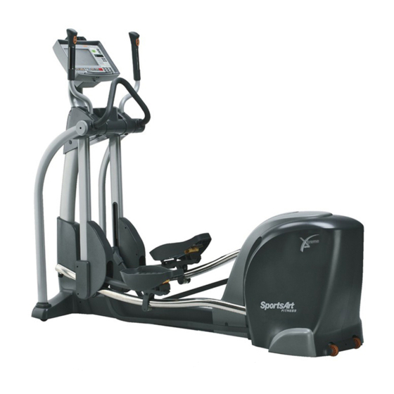
- 1 E870 Elliptical Trainer Unit Picture
- 2 E870 Components - (1) Display Area Components
- 3 E870 Components - (2) Back Area Components
- 4 E870 Introduction - Specifications
- 5 E870 Error Message: Service Battery (Continued through 6-2-3)
- 6 E870 Error Message: Unit will Not Turn on (Continued through 6-3-3)
- Download this manual
See also:
Owner's Manual
Advertisement
Table of Contents

Subscribe to Our Youtube Channel
Related Manuals for SportsArt Fitness E870


Summary of Contents for SportsArt Fitness E870
- Page 1 E870 Elliptical Trainer Repair Manual SPORTS ART INDUSTRIAL CO., LTD.
-
Page 2: Table Of Contents
【Table of Contents】 1. Component Placement 1-1-1. E870 Elliptical Trainer Unit Picture 1-1-2. E870 Components – (1) Display Area Components 1-1-3. E870 Components – (2) Back Area Components 1-1-4. E870 Components – (3) Display Board (Front) 1-1-5. E870 Components – (4) Display Board (Back) 1-1-6. - Page 3 5-2-1. E870 Drive Board Cable Connection Block Diagrams 5-2-2. E870 Drive Board Component Placement 5-2-3. E870 Drive Board Indicator Placement and Definitions 5-2-4. E870 Drive Board Indicator Placement and Definitions (Continued) 5-2-5. E870 Drive Board Cable Connector Placement and Definitions Continued on the following page.
- Page 4 6-5-1. E870 Error Message: Telemetry heart rate malfunction (Continued through 6-5-3) 6-6-1. E870 Error Message: Heart Touch Rate malfunction (Continued through 6-6-3) 6-7-1. E870 Error Message: Resistance is too low or too high (Continued through 6-7-3) 6-8-1. E870 Error Message: Stride length does not adjust (Continued through 6-8-3) 6-9-1.
- Page 5 7-3-1. E870 Optic Sensor Voltage Test (Continued through 7-3-2) 7-4-1. E870 Stride Voltage Test (Continued through 7-4-2) 7-5-1. E870 Stride Motor Voltage Test at the Drive Board (Continued through 7-5-2) 7-6-1. E870 Electro-Magnet Voltage Test at the Drive Board (Continued through 7-6-2) 7-7-1.
- Page 6 【Table of Contents】 8. Mechanical Component Adjustment and Replacement 8-1. Rear Cover Removal Procedure 8-2. Drive Pulley Adjustment 0-0-5...
-
Page 7: E870 Elliptical Trainer Unit Picture
1. E870 Elliptical Trainer Unit Picture 1-1-1... -
Page 8: E870 Components - (1) Display Area Components
2. E870 Components – (1) Display Area Components Display Stride Remote Key Level Remote Key HTR Contact (right) HTR Contact (Left) Stride Support Assembly 1-1-2... -
Page 9: E870 Components - (2) Back Area Components
2. E870 Components-(2) Back Area Components Batteries Alternator Drive Board Electro- magnet Optic Sensor 1-1-3... -
Page 10: E870 Components - (3) Display Board (Front)
3. E870 Components – Display Board (Front) 1-1-4... -
Page 11: E870 Components - (4) Display Board (Back)
3. E870 Components – Display Board (Back) 1-1-5... -
Page 12: E870 Components - Drive Board
4. E870 Components – Drive Board 1-1-6... -
Page 13: E870 Components - Other
5. E870 Components - Others Part Name Optic Sensor Part Name HTR Board Part Name HRC Board 1-1-7... -
Page 14: E870 Introduction - Specifications
1. E870 Introduction - Specifications ecifications Det ils Notes Power S upply AC Alter nator 1. Heart rate: 65%, 80%, Actual Heart Rate 2.Calorie s, Distance, Time, Strides/MIN Main Dis play Windows 3.Cal/ , Stride Length, Watts, Total Strides 5X8 2-co... -
Page 15: E870 Introduction - Display Windows
2. E870 Introduction – Display Windows Heart Rate Window 80% Target HR 65% Target HR Weight loss target Actual heart rate Cardio training heart rate target heart rate Stride/Min &Total Strides Calories & Cal/HR Window Window Calories: Total calories Stride/Min: average... -
Page 16: E870 Introduction - Display Keys And Indicators
3. E870 Introduction – Display Keys and Indicators Exercise Goal Keys Quick Start Key Flashing indicates Lit indicates exercise goal: Lit indicates activation of Quick Start heart rate reception time, distance, calories mode Exercise Program Keys Lit indicates Manual, Random, Plateau, Interval,... -
Page 17: E870 Introduction - Display Keys (Continued)
4. E870 Introduction – Display Keys (Continued) Display Lock/Unlock Key and Indicator Press to select active Exercise Goal Keys Quick Start Key feedback row. Top: Press to select exercise Press to operate in Quick Start mode calories, distance, goals: time, distance, calories (does not require user information) time, strides/minute;... -
Page 18: Operation
1. Start Up Function: Press Quick Start key or exercise to start up unit. Operation: (1) “SPORTSART – E870” scrolls across the display. After two seconds, “SELECT PROGRAM OR QUICKSTART” scrolls across the display. Press the Quick Start key to immediately start exercising, or press a program key to start exercising after entering user information. - Page 19 2. Workout Level Key Function: Set resistance level Operation: (1) Press the LEVEL <▲> key. The value in the Workout Level window increases. Actual resistance increases. (2) Press LEVEL <▼> key. The value in the Workout Level window decreases. Actual resistance decreases. (3) Workout level range: 1~20.
- Page 20 6. Display Lock/Unlock Key Function: Toggle between two rows of exercise feedback information Operation: (1) Press the <Display Lock/Unlock> key during exercise to toggle between exercise feedback views. Corresponding indicators light. Top row: calories, distance, time, strides/minute. Bottom row: Cal/hr, stride length, Watts, total strides. (2) In scan mode (the SCAN indicator lights);...
- Page 21 9. Basic Settings and Usage Information Function: (1) Determine basic settings (KM/MILE), see total distance and time in use, as well as display and drive board IC versions. Operation: (1) Press the <ENTER> key for three seconds to see basic settings. The message window shows present settings: “UNIT - MILE”...
- Page 22 10. Lubrication Mode Operating Procedure Function: (1) Grease the stride motor to ensure proper lubrication. Operation: (1) At start up, when “SELECT PROGRAM OR QUICKSTART” appears, simultaneously press <CALORIES>+<ENTER> keys for three seconds. The stride motor will automatically position itself to allow for lubrication.
-
Page 23: E870 Display Board Cable Connection Block Diagram
1. E870 Display Board Cable Connection Block Diagram Keys C-Safe Board Telemetry Board Display Board Board HTR Grip (Left, Right) Drive Board 4-1-1... -
Page 24: E870 Drive Board Cable Connection Block Diagram
2. E870 Drive Board Cable Connection Block Diagram Display Board Electro- Battery Magnet Drive Board DC 30V/1.5A Adaptor Optic Sensor AC Alternator Left Left Right Right Stride Stride Stride Stride Motor Motor 4-1-2... -
Page 25: E870 Display Board Cable Connection Block Diagram
1. E870 Display Board Cable Connection Block Diagram Keys C-Safe Board Telemetry Board Display Board Board HTR Grip (Left, Right) Drive Board 5-1-1... -
Page 26: E870 Display Board Component Placement
2. E870 Display Component Placement 5-1-2... -
Page 27: E870 Display Board Indicator Placement And Definitions
3. E870 Display Board Indicator Placement and Definitions POWER Indicator Lit indicates 5 VDC power supply COMM Signal Indicator Flashing indicates normal drive board signal processing 5-1-3... -
Page 28: E870 Display Board Cable Connectors And Definitions
4. E870 Display Board Cable Connectors and Definitions CON7 To 8-pin keypad CON6 To fan circuit board CON8 To 13-pin keypad CON4 CON3 CON9 To HTR board To HRC board To remote control CON5 To C-Safe board 5-1-4... -
Page 29: E870 Drive Board Cable Connection Block Diagrams
1. E870 Drive Board Cable Connection Block Diagram Display Board Electro- Battery Magnet Drive Board DC 30V/1.5A Adaptor Optic Sensor AC Alternator Left Left Right Right Stride Stride Stride Stride Motor Motor 5-2-1... -
Page 30: E870 Drive Board Component Placement
2. E870 Drive Board Component Placement 5-2-2... -
Page 31: E870 Drive Board Indicator Placement And Definitions
3. E870 Drive Board Indicator Placement and Definitions LED15 Display Board Power Indicator LED14 MOTOR Indicator Lit indicates drive board is sending 12 Lit indicates drive board is sending power to the incline VDC to display board LED1 INCL_L_UP LED (RED) -
Page 32: E870 Drive Board Indicator Placement And Definitions (Continued)
4. E870 Drive Board Indicator Placement and Definitions (Continued) LED12 CLK Indicator Flashing indicates arrival of optic sensor signal LED9 VR2_ERR Indicator ED11 VR1_ERR Indicator Lit indicates right stride VR error Lit indicates left stride VR error LED5 OVER_L Indicator... -
Page 33: E870 Drive Board Cable Connector Placement And Definitions
5. E870 Drive Board Cable Connector Placement and Definitions To display board To stride motors To battery To battery charger To electro-magnet and optic sensor 5-2-5... - Page 34 E870 Error Messages: ERR 7 1. Definition: (1) Display board CPU has not read the stride VR1/VR2 voltage. (2) Stride motor VR1/VR2 voltage exceeds the proper range, from 0.5 VDC to 4.5 VDC. 2. Block Diagram D isp la y B o a rd...
- Page 35 3. Operation Order Part Explanation 1. As the stride motor operates up or down, VR1/VR2 voltage value Stride Motor increases or decreases. 1. 22 VDC travels from the drive board to the stride motor. 10-pin Cable 2. VR1/VR2 voltage travels to the drive board. 1.
- Page 36 6. Troubleshooting Order Part Troubleshooting 1. When the drive board VR1_ERR indicator lights, inspect the left stride VR. When the drive board VR2_ERR indicator lights, inspect the right stride VR. 2. Measure the VR1 or VR2 voltage. Normal range: 0.6-4.45 Stride VR VDC.
-
Page 37: E870 Error Message: Service Battery (Continued Through 6-2-3)
E870 Error Message: Service Battery 1. Definition: Battery voltage is below 22 VDC. 2. Block Diagram D isplay Board Battery Signal F2 1A Battery Signal C N4 Battery D rive Board 2 PIN 6-2-1... - Page 38 3. Operation Order Part Explanation Battery 1. The battery receives and provides voltage. 2-pin Cable 1. Battery voltage travels to the drive board. 1. Drive board CPU reads and detects whether battery voltage is Drive Board too low. 1. The battery voltage signal travels from the drive to the display 16-pin Cable board.
- Page 39 6. Troubleshooting Order Part Troubleshooting 1. Test whether the battery has less than 22 VDC. If so, exercise on the unit for at least half an hour at more than 30 Battery STEPS/MIN. 2. Replace the battery as a test. 2-pin Cable 1.
-
Page 40: E870 Error Message: Unit Will Not Turn On (Continued Through 6-3-3)
E870 Error Message: Unit will not turn on. 1. Circumstance of Malfunction: Press the QUICK START key or exercise on the unit. The display does not beep and fails to light up. 2. Block Diagram Display Board F2 1A Battery... - Page 41 3. Operation Orde Part Explanatio 1. The ernator provides power to replenish the battery. 1. Volt travels from the battery to the drive board. 2-pin Cabl 2. Voltag travels from the alternator to the battery. 1. If altern ator voltage is too high, the fuse blows, protecting F1 use the batt y and drive board U8 IC.
- Page 42 5. Troubleshooting Orde Troublesho oting 1. Me asur e battery voltage. If less than 22 VDC, exercise at over 30 STEPS/ MIN for more than 30 minutes to replenish the battery. B tery 2. Repl the battery as a test. Cable 1.
-
Page 43: E870 Error Message: Soft Key Malfunction (Continued Through 6-4-2)
E870 Error Message: Soft key malfunction 1. Circumstance of Malfunction: (1) Start up unit. Do not press any keys. Display beeps and operates as if keys had been pressed. (2) Press the display keys. There is no reaction after keys are pressed. - Page 44 3. Operation Orde Explana tion 1. W you press a key, the key circuit has continuity. The key operat 1. TIME, DIST, CAL, and POWER ON signal travel to the display board. 1. Numb er, ENTER, and PROGRAM signals travel to the display able board.
-
Page 45: E870 Error Message: Telemetry Heart Rate Malfunction (Continued Through 6-5-3)
E870 Error Message: Telemetry heart rate malfunction 1. Circumstance of Malfunction: (1) There is no heart rate reading. (2) Heart rate reading is inaccurate. 2. Block Diagram Telemetry Telemetry Display Receiver Board Transmitter 3PIN Board Strap CON3 6-5-1... - Page 46 3. Normal Operation Order Part Operation 1. The telemetry heart rate transmitter detects the human Telemetry Heart Rate heart rate and transmits the heart rate signal to the receiver Transmitter board. 1. The telemetry heart rate receiver board receives the signal Telemetry Heart Rate and transmits the signal to the display.
- Page 47 5. Troubleshooting Order Part Procedure lemetry Insp ect the transmitter: Is it a SportsArt transmitter. rans mitter lace the transmitter as a test. Te m le etry Receiver 1. Ins pect the telemetry heart rate receiver: Is it fastened Board secure 2.
- Page 48 E870 Error Message: Heart Touch Rate (HTR) malfunction 1. Circumstance of Malfunction: (1) Place both hands on the HTR contacts. Display does not show a heart rate value. (2) Do not place hands on the HTR contacts. Display shows a heart rate value.
- Page 49 3. Operation Part Order Explanation 1. Hold onto the HTR contacts with both hands. Handlebar 2. The contacts detect heart rate. HTR 2-pin 1. The heart rate signal travels the left and right HTR cables to 5-pin Cable cable. 5-pin Cable 1. The HTR board signal travels this cable to the HTR board. 1.
- Page 50 5. Troubleshooting Orde Troubles hooting Clean the HTR contact pads. tacts 2. Test e HTR cable. in Ca 1. Ins t whether the cable is not connected or is broken. in Ca 1. Ins t whether the cable is not connected or is broken. 1.
-
Page 51: E870 Error Message: Resistance Is Too Low Or Too High (Continued Through 6-7-3)
E870 Error Message: Resistance is too low or too high 1. Circumstance of Malfunction: (1) Turn on unit. Exercise. Press LEVEL ▲/▼ keys. Resistance does not change or there is no resistance. (2) Turn on unit. Resistance is so high the machine cannot be used. - Page 52 3. Operation Orde Operation 1. V oltag e from the drive board makes the electro-magnet Elect ro- agnet attract the flywheel. The higher the voltage, the greater the attraction. 1. The v oltage travels from the drive board to the electr -magnet.
- Page 53 5. Troubleshooting Order Part Troubleshooting 1. Is there voltage to the electro-magnet during use. tro-Magnet 2. In spect whether the electro-magnet has an electrical short or open. 3. R eplace the electro-magnet as a test. 2-pi n Cable 1. I spect whether the cable is not connected properly or is broken. 1.
-
Page 54: E870 Error Message: Stride Length Does Not Adjust (Continued Through 6-8-3)
E870 Error Message: Stride length does not adjust. 1. Circumstance of Malfunction: 1. Press Stride▲/▼ keys. Values in the display stride window change but the stride motor does not operate. 2. Block Diagram D isp la y B o a rd... - Page 55 3. Operation Order Part Operation 1. M ovement of stride motors changes the stride length. Strid e Motor ot r movement changes the VR output voltage. VR output voltage (Lef /Right) elates to stride motor position, which correlates to stride length. 1.
- Page 56 5. Troubleshooting Troubleshooting 1 Inspect whether cables are not connected properly or are broken. t/Right Inspect whether stride motors receive voltage when stride keys are ide Motors ssed. Replace the stride motor as a test. 10-pin Cable 1. Inspect whether cables are not connected properly or are broken. 1.
-
Page 57: E870 Error Message: No Step Count
E870 Error Message: No Step Count 1. Circumstance of Malfunction: Exercise on the product. The STRIDES/MIN window on the display does not show any step count. 2. Block Diagram Display Board Optic Sensor 3PIN Drive Board LED12_CLK 6-9-1... - Page 58 3. .Operation Orde Part Explanatio 1. Th e dr ive board supplies all VBB power supply to the Drive Boa display board. 2. The dri ve board receives the optic sensor signal. 1. When someone exercises on the unit, the CLK signal is Optic en transmitte d to the drive board.
- Page 59 4. Troubleshooting Orde Troublesh ooting 1. Ins pect drive board CN2, CN3 cable connections. 2. Inspect drive board U8 IC connections. Replace as a test. Driv Boa 3. Replac e the drive board as a test. 1. Inspect whether the CLK signal when someone exercises. sor 2.
- Page 60 E870 Battery Voltage Test 1. Test Configuration 7-1-1...
- Page 61 2. Test Procedure (1) Put voltmeter to the 200 VDC setting. Place one probe on the battery red terminal. Place the other probe on the battery black terminal. (2) Display shows 24~25 VDC. (3) If the battery has less than 22 VDC, “SERVICE BATTERY” appears on the display, indicating that battery voltage is too low.
- Page 62 E870 Alternator Voltage Test 1. Test Configuration 7-2-1...
- Page 63 2. Test Procedure (1) Put the voltmeter to the 200 VAC setting. Place probes separately on alternator yellow-yellow or yellow-white wires. (2) Exercise on the unit. Compare readings. See normal reading below. (3) If there is no consistent AC voltage output, the battery cannot be recharged and the electro-magnet cannot operate.
- Page 64 E870 Optic Sensor Voltage Test 1. Test Configuration Fig. 1. Distance between optic sensor & reflective tape Fig. 2. Probe positions Reflective Sticker Infrared Sensor 3-7 mm Black Yellow Optic sensor board 7-3-1...
- Page 65 2. Test Procedure (1) Optic sensor to reflective sticker distance test Make sure that the infrared optic sensor is within 3-7 mm from the reflective sticker, as shown in Fig. 1. (2) Optic sensor signal test Put voltmeter to the 20 VDC setting. Place probes separately on optic sensor wire connectors. Exercise on the unit.
- Page 66 E870 Stride Voltage Test 1. Test Configuration Stride Motor Voltage Test Configuration Stride VR Voltage Test Configuration 7-4-1...
- Page 67 2. Test Procedure (1) Please see the stride motor connector illustration, Fig. 1. (2) Stride motor voltage test: Turn on unit. Exercise. Press the STRIDE key to test as indicated. (3) The stride VR voltage test: Turn on unit. Normal voltage specifications are shown in Chart 2. (4) If there is no stride motor voltage when exercising, stride length will not adjust.
- Page 68 E870 Drive Board Stride Motor Voltage Test P9 +22V hoop 1. Test Configuration LED14 motor indicator P4 GND hoop 7-5-1...
- Page 69 2. Test Procedure (1) Put voltmeter to the 200 VDC setting. Place probes separately on drive board P9 +22V and P4 GND test hoops. (2) Normal reading: 22~23 VDC. (3) If no power is emitted from the drive board, stride motors cannot operate. Put black probe on ground hoop.
- Page 70 E870 Electro-Magnet Voltage Test at the Drive Board 1. Test Configuration LED15 +12V LED13 VCC P7 L1 Hoop P4 GND Hoop 7-6-1...
- Page 71 2. Test Procedure (1) Put voltmeter to the 20 VDC setting. Place probes on the drive board P7 L1 and P4 GND hoops. (2) Exercise on the unit. Normal readings are shown in the chart below. (3) If the drive board does not provide voltage to the electro-magnet, there will be no resistance. Put the red probe on P7;...
- Page 72 E870 VCC Voltage Test at the Drive Board 1. Test Configuration LED13 VCC indicator P10 VCC hoop P4 GND hoop 7-7-1...
- Page 73 2. Test Procedure (1) Put voltmeter to the 20 VDC setting. Place probes separately on drive board P10 VCC and P4 GND hoops. (2) Normal reading: 5±0.1 VDC. Put place probe on GND hoop. Place red probe on VCC hoop. Normal reading: ~5 VDC.
- Page 74 E870 VBB Voltage Test at the Drive Board 1. Test Configuration LED15 VBB indicator P11 VBB hoop P4 GND hoop 7-8-1...
- Page 75 2. Test Procedure (1) Put voltmeter to the 200 VDC setting. Place probes separately on P11 VBB and P4 GND hoops on the drive board. (2) Normal reading: 12~13 VDC. Put the black probe on the GND1 hoop. Put the red probe on the VDD hoop. Normal reading: ~12 VDC.
- Page 76 E870 Electro-Magnet Voltage Test at the Drive Board 1. Test Configuration LED15 VBB indicator P2 VDD hoop LED13 VCC indicator P4 GND hoop 7-9-1...
- Page 77 2. Test Procedure (1) Put voltmeter to the 200 VDC setting. Place probes separately on drive board P2 VDD and P4 GND hoops. (2) Normal reading: 31~32 VDC. Put black probe on P4 GND hop. Put red probe on P2 VDD hoop. Normal reading: ~31 VDC. 3.
- Page 78 E870 Battery Voltage Test at the Drive Board P1 VBAT hoop 1. Test Configuration LED15 VBB indicator LED13 VCC indicator P4 GND hoop 7-10-1...
- Page 79 2. Test Procedure (1) Put voltmeter to the 200 VDC setting. Put probes separately on P1 VBAT and P4 GND hoops on the drive board. (2) Normal reading: 25.5~26 VDC. Put the black probe on P4 GND hoop. Put the red probe on P2 VBAT hoop. Normal reading: ~25 VDC.
- Page 80 E870 VBB Voltage Test at the Display Board 1. Test Configuration POWER indicator COMM indicator 7-11-1...
- Page 81 2. Test Procedure (1) Turn on unit power. Display board POWER indicator lights. The COMM indicator flashes. (2)Put voltmeter to the 20 VDC setting. Place probes as shown. (3) Normal reading: 12±0.3 VDC. 3. Troubleshooting If the display POWER indicator lights and there is not 12±0.3 VDC, inspect the following: (1) Is the data cable connected properly at the drive and display boards? (2) Is the data cable broken? (3) Replace U20 LM2576 or D42 HER305 on the drive board as a test.
- Page 82 E870 VCC Voltage Test at the Display Board 1. Test Configuration POWER indicator COMM Indicator 7-12-1...
- Page 83 2. Test Procedure 1. Turn on unit power. The POWER LED on the display lights. The COMM indicator flashes. 2. Put voltmeter to the 20 VDC setting, place probes as shown. 3. Normal reading: 5 VDC±0.2V. 4. Display beeps once and lights up. 3.
- Page 84 E870 Fan Voltage Test at the Display Board 1. Test Configuration POWER LED 7-13-1...
- Page 85 2. Test Procedure (1) Press the <ON> key or exercise on the unit. Display POWER indicator LED lights. (2) Press the QUICK START key to operate the unit. Press the FAN key to toggle through fan settings: low, medium, high, off. (3) Dot matrix display shows “FAN-LOW”, “FAN-MID”, “FAN-HIGH”, “STOP”.
- Page 86 E870 Remote Key Test Procedure (Display CON9 Cable to Left/Right Remote Control Keys) Fig. 1. Test Configuration Fig.2. Remote Keys Left Remote Level Key Right Remote Level Key 7-14-1...
- Page 87 2. Test Procedure (1) Do not turn on the unit. Remove the display cover to access the CON9 cable on the display board. (2) Put voltmeter to the 200Ω setting. Place probes as shown in Fig. 1, a general view, and Fig. 3, an illustration of the CON9 cable connector wires.
- Page 88 HTR Cable (5-pin to HTR Left and Right Contacts) Test Fig. 1: Place black probe as indicated Fig. 2: Place red probe as indicated on HTR contacts A-->Right HTR Contact B-->Left HTR Contact (Note: There are three wires on the HTR board 5-pin cable.) 7-15-1...
- Page 89 2. Test Procedure (1) Do not turn on unit power. Remove display cover to access the HTR board 5-pin cable. (2) Put voltmeter to the 200 ohm setting. Place probes as shown in Fig. 1 and 2. Test HTR cable and ground for electrical shorts and opens. (3) Test as shown below.
- Page 90 E870 Telemetry Heart Rate Receiver Board Test Actual Heart Rate Telemetry Strap 7-16-1...
- Page 91 2. Test Procedure (1) Put the telemetry heart rate strap in place. (2) Press the QUICK START key and start exercising. Exercise with the telemetry strap within two feet from the display. (3) Within five seconds, the display shows the heart rate value. If no heart rate value appears, refer to troubleshooting.
- Page 92 E870 HTR Board Test 1. HTR Board Indicator LED Placement and Definitions LED3 LED4 LED2 LED1 2. Indicator Definitions Color Name Explanation LED1 Telemetry Indicator Flashing indicates incoming telemetry heart rate signal. LED2 Orange HTR Contact Lit indicates hands are holding HTR contacts.
- Page 93 2. Test Procedure The following indicates normal heart rate operation. 1. Do not hold onto the HTR handlebar. HTR board indicators do not light. 2. Hold onto the HTR handlebar with both hands. The HTR board LED2 indicator lights. 3. LED3 indicator flashes, indicating an incoming HTR handlebar signal. 4.
- Page 94 E870 Electro-Magnet Electrical Short Test 1. Test Configuration Fig. 1: Test Configuration Fig. 2: Electrical Short Test Wire-to-Cover Electrical Short Test 7-18-1...
- Page 95 2. Test Procedure (1) Electrical open test: Put voltmeter to the 200 Ω setting. Place probes as shown in Fig. 1. Normal test results are shown below. Note: a reading of just under 20Ω indicates the electro-magnet is OK. (2) Electrical short test: Put voltmeter to the 20 MΩ setting. Place probes as shown in Fig. 2. Normal test results are shown below.
- Page 96 E870 AC Alternator Electrical Short and Open Test 1. Test Configuration Fig. 1: Electrical Open Test Fig. 2: Electrical Short Test Place probes as shown. 7-19-1...
- Page 97 2. Test Procedure (1) Electrical Open Test: Put voltmeter to the 200Ω setting. Place probes as shown in Fig. 1. Normal readings are shown below. (2) Electrical Short Test: Put voltmeter the 20MΩ setting. Place probes as shown in Fig. 2. Normal readings are shown below.
- Page 98 E870 Rear Cover Removal Procedure Remove screw soft covers. 2. Remove left/right side small covers. 3. Remove 9 screws. 4. Remove rear cover. 8-1-1...
- Page 99 E870 Rear Cover Removal Procedure 1. Remove screw soft covers. 2. Lift to remove L/R side small covers. 3. Remove screws from both sides. 4. Remove screw from back. 8-1-2...
- Page 100 E870 Rear Cover Removal Procedure 5. While lifting the cover from the front about 45 6. This shows the completed procedure. degrees, push toward the back. 8-1-3...
- Page 101 E870/E880 Drive Belt Tension Adjustment Adjustment Circumstances: After replacing a flywheel or after a long period of use, the drive belt may be too loose, requiring adjustment. Step 1. Use an 8 mm Allen wrench to screw the adjustment nut clockwise.
- Page 102 E870/E880 Drive Pulley Adjustment Procedure 1. Use an 8mm allen wrench to screw in the adjustment screw. 2. Measure spring top/bottom distance. Adjust to Turn clockwise to tighten. 56 mm length. 約 56mm Notes: 1. After replacing a flywheel, first adjust spring top/bottom distance to 56mm. Inspect whether the belt still slips.
Need help?
Do you have a question about the E870 and is the answer not in the manual?
Questions and answers