Advertisement
Quick Links
Advertisement

Subscribe to Our Youtube Channel
Related Manuals for SportsArt Fitness G875


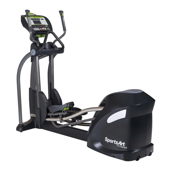
Summary of Contents for SportsArt Fitness G875
- Page 1 G875 Repair manual (Electronics)
- Page 2 1-1. Product-G875 1-1-1...
- Page 3 1-2. Display -G875 1-2-1...
- Page 4 1-3.Component placement - G875 Display USB board Control board Wireless HR board Program board 1-3-1...
- Page 5 1-3.Component placement - G875 Frame Generator Power Incline board board Flywheel MI drive board 1-3-2...
- Page 6 1-3.Component placement- G875 Frame 1-3-3...
-
Page 7: C-Safe Board
1-4. Block diagram -G875 USB Board keypad Display C-SAFE Board Board HR board Sensor-L HTR board Stride / Level key Sensor-R Power board Stride motor (L) Fuse AC1, AC2 Stride VR (L) Stride motor (R) Drive Board Stride VR (R) - Page 8 1-5.Wiring diagram -G875 1-5-1...
-
Page 9: Control Board
1-5.Wire connections -G875 Display To USB board Control board To drive board To fan To USB board & CSAFE board To key pads Program board To USB board To POLAR board To HTR board 1-5-2... - Page 10 1-5. Wire connections -G875 Display USB board CON3 CON1 To control board To control CON2 board Bluetooth key CON3 CON4 CON5 To program board CON1 CON2 CON6 1-5-3...
- Page 11 1-5. Wire connections -G875 MI drive board To power board To incline board To generator 1-5-4...
- Page 12 1-5. Wire connections -G875 MI drive board Incline board wires Power board wires To control board To incline To MI drive board board To power board To MI drive board 1-5-4...
- Page 13 1-6. LED indicator -G875 Display LED16 POWER indicator LED18 COMM communication indicator 1-6-1...
- Page 14 1-6.LED indicator -G875 MI drive board LED 3 COMM communication indicator Program 1-6-2...
- Page 15 1-6.Commnucation indicators – Incline board Stride down indicators LED 1 INCL_DN_R LED 4 INCL_DN_L Lit,right stride decrease Lit,left stride decrease Stride up indicators LED 1 INCL_UP_R LED 3 INCL_UP_L Lit,right stride Lit,left stride increase increase 1-6-3...
- Page 16 1-7. Electronic component specification -G875 Description Note Specification Power source AC 110V / 220V Main power Generator power AC generator source Max output WATT =250 W Resistance circuit inside the MI drive board to control generator Resistance control LEVEL 1 – LEVEL 40...
- Page 17 2-1.Troubleshooting -G875 Faulty item Description Inspect and test procedures Suggesting replacement parts No power Display is not lit up while 1.Check all wire connections 1. Product fuse pedaling the bike 2. Check product fuse 2. Power board 3.Check power board 3.
- Page 18 No fan Pressing <FAN> button and 1. Check fan wiring 1. Control board fan is not functioning 2. Check fan voltage output on the control board 2. Fan 3. Replace control board 4. Replace fan ERROR_1_1 Display showing 1. System power on abnormal 1.
- Page 19 ERROR_3_3 Display showing 1. Abnormal frequency from outside power source 1.MI drive board “ERROR_3_3” when power 2. Check power source frequency 3. Or replace MI drive board to test ERROR_3_4 Display showing 1. AC power mid-point error; this is for MI drive 1.MI drive board “ERROR_3_4”...
- Page 20 ERROR_8_1 Display showing 6. Communication error “ERROR_8_1” when power 7. Check control board and program board ERROR_8_2 Display showing 1. Communication error “ERROR_8_2” while 2. Check control board and program board exercising 3. Product self-protection from interference; turn power off/on to test Total distance display Kph/mph/total Press <CHANGE DISPLAY>...
- Page 21 Troubleshooting Model no.: G875 Malfunction item: Product will not turn on POWER1 Fuse, Switch Circumstance: Start pedaling, display will not turn on Possible causes: 1.Bad wire connections 2. Bad power board 3. Bad MI drive board 4. Bad control board Troubleshooting: 1.Check product fuse...
- Page 22 Troubleshooting Model no.: G875 Key pads Malfunction item: No Stride/min display Circumstance: No RPM display while pedaling the bike Possible causes: 1.Control board or drive board shut down 2. Bad wiring on generator 3. Bad MI drive board Troubleshooting: 1.Turn power off/on to test 2.
-
Page 23: Troubleshooting
Troubleshooting Model no.: G875 Malfunction item: No resistance Energy reference Circumstance: No resistance while pedaling the bike Workout Watt Possible causes: 1.Resistance is coming from MI drive board level resistance control circuit controlling generator 2. Generator drive belt tension issue or bad generator 128W 3.Bad MI drive board... - Page 24 Troubleshooting Model no.: G875 Malfunction item: Bad telemetry heart rate reception Circumstance: Bad telemetry heart rate reception Possible causes: 1.Telemetry transmitter battery too low 2. Bad HR receiver board Wireless HR board 3. Interference issue, such as lights, speakers Troubleshooting: 1.Replace the transmitter battery 2.
-
Page 25: Htr Board
Troubleshooting Model no.: G875 HTR board LED indicator Malfunction item: Bad HTR signal Indicator Name Description Circumstance: Holding to HTR and the reading is incorrect LED1 Telemetry Flashes to indicate incoming telemetry signal Possible causes: 1. Bad HTR wire connections... - Page 26 Troubleshooting Model no.: G875 Malfunction item: bad keys – soft key pads Circumstances: No response when pressing keys Possible causes: 1.Bad membrane key pads Troubleshooting: 1.Replace membrane key pads Display board Soft key 3-5-1...
- Page 27 Troubleshooting Model no.: G875 Malfunction item: Bad key - display Circumstance: No response while pressing the display keys Possible causes: 1. Bad display tact switches 2. Bad switch sleeve placement Troubleshooting: 1.Check switch sleeves 2. Replace display tact switches Switch sleeves...
- Page 28 Troubleshooting Model no.: G875 Wire connections for handrails Malfunction item: Bad key pads- handrail stride, level <▲>,<▼> Circumstance: No response when pressing the keys on the handrails Possible causes: 1.Bad wire connection on the handrails 2. Bad key pads Troubleshooting: 1.Check wire connections on console &...
- Page 29 Troubleshooting Model no.: G875 Malfunction item: Fan does not operate correctly Circumstance: 1.Press the fan key & fan is not responding Possible causes: 1.Bad control board 2. Bad fan wire connections or bad fan motor Troubleshooting: 1.Check the fan key and wire connections 2.Measure control board fan voltage...
- Page 30 Troubleshooting Model no.: G875 Malfunction item ERROR_1_1 POWER1 Circumstance: Display showing “ERROR_1_1” when power on Possible causes: 1.Bad MI drive board 2.Bad Control board to MI drive board Troubleshooting: 1.ERROR_1_1 means power on error 2.Check wiring from control board to MI drive board 3.Check DSP MI driver on the MI drive board...
- Page 31 Troubleshooting Model no.: G875 Press & hold “workout level<▲> & <▼> & <display Malfunction item: ERROR_1_6 change> to set model no. and AC VOLTAGE Circumstance: Display showing “ERROR_1_6” when power on Possible causes: 1.Product voltage setting incorrect Troubleshooting: 1.Press & hold “workout level<▲> & <▼> & <change display>...
- Page 32 Troubleshooting Model no.: G875 Malfunction item: ERROR_2_1, ERROR_2_2 POWER1 Circumstance: Display showing “ERROR_2_1 or 2_2” when power on Possible causes: 1.Bad MI driver 2.Bad control board to MI drive board Troubleshooting: 1.ERROR_2_1 means MI driver IGBT over current ERROR_2_2 means MI driver IGBRT too hot 2.
- Page 33 Troubleshooting Model no.: G875 Malfunction item: ERROR_3_1 POWER1 Circumstance: Display showing “ERROR_3_1” when power on Possible causes: 1.Broken AC power cord 2.The time between Power off & on is too short 3. Bad MI driver Troubleshooting: 1.ERROR_3_1 means Islanding 2.Check power cord 3.Make sure there is 5 seconds in between power off/on/...
- Page 34 Troubleshooting Model no.: G875 Malfunction item: ERROR_3_2 POWER1 Circumstance: Display showing “ERROR_3_2” when power on Possible causes: 1.Power source voltage is over the limit Troubleshooting: 1.Proper voltage range 110V 105 – 132 Vac 220V 184 – 264 Vac 2.Check power source voltage range...
- Page 35 Troubleshooting Model no.: G875 Malfunction item: ERROR_3_3 POWER1 Circumstance: Display showing “ERROR_3_3” when power on Possible causes: 1.Abnormal power source frequency 2.Bad MI drive board Troubleshooting: 1.This message is a self-protective function. Usually it will Not occur. 2.Check power source frequency 3.Replace drive board to test...
- Page 36 Troubleshooting Model no.: G875 Malfunction item: ERROR_3_4 POWER1 Circumstance: Display showing “ERROR_3_4” when power on or exercising Possible causes: 1.Power source interference or irregular 2.Bad MI drive board Troubleshooting: 1.ERROR_3_4_ means the AC voltage mid-point error 2.Check power source regularity 3.Replace MI drive board to test...
- Page 37 Troubleshooting Model no.: G875 Malfunction item: ERROR_3_5 POWER1 Circumstance: Display showing “ERROR_3_5” when power on or exercising Possible causes: 1.Power cord grounding issue 2.Improper power source grounding Troubleshooting: 1.ERROR_3_5 means AC power grounding failing 2.Check power cord installation 3.Check power system for proper grounding...
- Page 38 Troubleshooting Model no.: G875 Malfunction item: ERROR_4_3,ERROR_4_4 POWER1 Circumstance: Display showing “ERROR_4_3,4_4” when power on or exercising Possible causes: 1.Power source interference 2.Bad MI drive board Troubleshooting: 1.”ERROR_4_3” means DC BUS voltage too high “ERROR_4_4” means DC BUS error 2.Turn power off & on to test 3.Check power source voltage irregularity...
- Page 39 Troubleshooting Model no.: G875 Malfunction item: ERROR_5_1,ERROR_5_2 POWER1 Circumstance: Display showing “ERROR_5_1,5_2” when power on or exercising Possible causes: 1.MI drive board self-protective function 2.Bad MI drive board Troubleshooting: 1.”ERROR_5_1” means MI drive board is forced to warm up “ERROR_5_2” means MI drive board is forced to shut down(Emergency stop)...
- Page 40 Troubleshooting Model no.: G875 Malfunction item: ERROR_6_1, 6_2, 6_3 POWER1 Circumstance: Display showing “ERROR_6_1, 6_2, 6_3” when exercising Possible causes: 1.Abnormal generator 2.Bad MI drive board Troubleshooting: 1.ERROR_6_1 means generator over current ERROR_6_2 means generator voltage error ERROR_6_3 means generator too hot (reserved for this function) 2.Chech generator wire connections;...
- Page 41 Troubleshooting Model no.: G875 Malfunction item: ERR7 Circumstance: 1.Error message showing ERR7-INCLINE-R or ERR7-INCLINE-L Possible causes: 1.Bad STRIDE incline VR Troubleshooting: 1.Use the console auto VR range checking Function to see if it is over the range ERR7-INCLINE-R: Right side problem ERR7-INCLIME-L: Left side problem 2.
- Page 42 Troubleshooting Model no.: G875 Malfunction item: ERROR_8_1 POWER1 Circumstance: Display showing “ERROR_8_1” when power on Possible causes: 1.Bad MI drive board 2. Bad control board Troubleshooting: 1. Check control board & MI drive board wire connections 2.Check control board & MI drive board IC program board installation 3.Replace control board &...
- Page 43 Troubleshooting Model no.: G875 Malfunction item: ERROR_8_2 POWER1 Circumstance: Display showing “ERROR_8_2” while exercising Possible causes: 1.Communication interference 2.Programm not installed correctly Troubleshooting: 1.Check wiring (Between control board & MI drive board) 2.Product self-protective function. Turn power off/on to test 3.Replace control board and MI drive board to test...
- Page 44 Other item Model no.: G875 Item: Lubrication operation Steps: 1.Press and hold<ENTER> & <CALORIES> keys for 3 seconds to enter lubrication sequence. a. Display b. Stride incline motor will move up to the lubrication position. Add lubricant 2. When finish, turn the power switch on/off twice and the stride motor will return to its starting position to complete the process.
- Page 45 Other item Model no.:G875 Item:Other functions Descriptions: 1.Idle mode Display will get into idle mode when no pedaling for 2 minutes. There is no power to the display at this time, only MI drive board EUP circuit consumes power. 2.Power on Pedal bike while in sleep mode to turn on power.
- Page 46 Model no.:G875 Item:Model no. & power source voltage setting Description:1.G575R/U,& G875 use the same control board and software version. There is no model no. board. You may set the model no. via software. To use this function, the control boardCTL version has to be 2B & MI drive board version- 4252 2.Setting procedures...
- Page 47 Other item Model no.:G875 Item: MI Drive board voltage setting Description:1.MI drive board version is before 4252(Before May, 2014) 2.Set power source voltage 110V 220V 3-18-1...
- Page 48 Other item Model no.:G875 Item:Error messages Description:ERROR_1_1 System power on error ERROR_1_6 Power source voltage setting error ERROR_2_1IGBT over current (DC bus over current) ERROR_2_2IGBT too hot ERROR_3_1AC power lost or time between power off/on is too short (Islanding)。 ERROR_3_2AC power source voltage error ERROR_3_3AC power source frequency error...
- Page 49 Other item Model no.: G875 Item: KPH/MPH switch, total distance, total time and software version display Method: 1. Press <CHANGE DISPLAY” for 3 seconds to get into user reference and setting mode A. English and Metric setting The display will show “UNIT-MPH” for English setting or “UNIT-KPH” for metric setting. Press INCLINE <▲>...
- Page 50 Other item Model no.: G875 Item: Language setting Description: How to set up the language preference, such as German, French… Method: 1. Press <CHANGE DISPLAY> for 3 seconds to enter user preference and setting mode. Continuing pressing <ENTER > key, the display will show “UNIT-KPH, MPH;TIME LITMIT ; ZZZ TIME-XXMIN”…until the display shows ”GERMAN ”or “...
- Page 51 Other item Model no.: G875 Item: Electronic component specification Description 3-22-1...
- Page 52 Other item Model no.: G875 Item: stride incline motor calibration Method: 1.stride incline motor calibration procedure Step1.The voltage between Black & White wires on the VR is about 4.1V Step2. The travel distance is 30-35mm Step1.figure A,voltage setting 4.1V (Black-white wires)
- Page 53 Inspection & measurement Item: Alternator/generator Testing item: Power generated voltage inspection Method: 1.Visually inspection A.Check generator wire connections B.Check generator belt tension C.Check generator pulley installation RPM=60, LEVEL 20 2.Measure voltage “WATTS to the Grid”= 136 A.Pedal bike once per second, RPM reading should be 60 B.When RPM is 60 at LEVEL 20, the ”WATTS TO THE GRID”window should show 136W.
- Page 54 Inspection & measurement Item: power board inspection Testing item: power source voltage inspection Power board wires Method: 1. Input voltage Blue – brown wires: AC 110V or 220V 2. Output voltage Black/brown to yellow & orange: DC 12V Output Blue - green DC 22V Black - red ...
- Page 55 Inspection & measurement Item: MI drive board Testing item: stride/min measurement Method: 1. There is stride/min detecting circuit inside MI drive board. It will detect the AC voltage and figure out the stride/min value. 2.Pedal once per second, the stride/min reading should be about 60. 3.If the reading is off a lot, check generator pulley &...
-
Page 56: Communication Indicator
4-3-1 Inspection & measurement Item: MI drive board Testing item: MI drive board communication Method: 1. Turn on the power and visually inspect the LED3 indicator flashing status. Normally, it is flashing regularly. If irregular flashing occurs, it means there is a communication error; check wiring connections at this time LED 3 COMM Communication indicator 4-4-1... - Page 57 Inspection & measurement Item: MI drive board Testing item: Power generated measurement Method: 1. There is a circuit inside the MI drive board which will calculate the voltage generated. Pedaling & level setting, the “WATTS TO GRID” window display as below - LEVEL WATTS 128W...
- Page 58 Inspection & measurement Item: Stride incline motor assembly Testing item: Measure VR voltage Method: 1. Set voltage meter to 20V setting 2. Put the red/black led to stride incline motor VR black/white wires to obtain the voltage reading. Press Stride<▲>/<▼> to adjust the stride value and the voltage reading should be: Stride VR(Left) VR(Right)
- Page 59 Inspection & measurement Item: Stride incline motor assembly Testing method: Measure the incline motor voltage Method: 1. Set the volt meter to above 30V 2. Put the red/black led to the brown & blue wires on the incline motor VR to obtain the voltage reading. Press Stride<▲>/<▼>...
Need help?
Do you have a question about the G875 and is the answer not in the manual?
Questions and answers