Table of Contents
Advertisement
Quick Links
TN1412
Technical note
ACEPACK DRIVE assembly instructions
Introduction
This document describes the recommended process for mounting ACEPACK DRIVE power module: to meet the very high-
quality standard requested by the automotive environment. Purpose of this document is summarize the best way to use the
module that drives the most critical part in the automotive environment, which is the traction inverter.
TN1412 - Rev 1 - May 2022
www.st.com
For further information contact your local STMicroelectronics sales office.
Advertisement
Table of Contents

Related Manuals for ST ACEPACK DRIVE


Summary of Contents for ST ACEPACK DRIVE
- Page 1 ACEPACK DRIVE assembly instructions Introduction This document describes the recommended process for mounting ACEPACK DRIVE power module: to meet the very high- quality standard requested by the automotive environment. Purpose of this document is summarize the best way to use the module that drives the most critical part in the automotive environment, which is the traction inverter.
-
Page 2: General Information
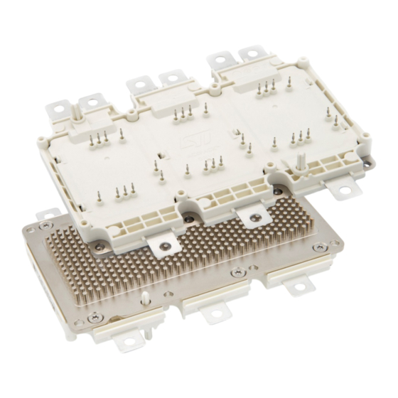
In the above picture, it is possible to see the ACEPACK DRIVE typical appearance. For the ACEPACK DRIVE power module, the press-fit pin is the kind of connection chosen to have the most reliable contact between the module and the driving board. The electrical and thermal contacts with the circuit board are implemented by means of cold welding when press-fit pins are used. -
Page 3: Figure 2. Materials Connected Together In A Gas-Tight Manner Due To The Press-In Force
To avoid any possible mistake during the assembly phase and to speed up the process X-pin & Y-pin implementing a poka-yoke concept has been adopted in the ACEPACK DRIVE power module: the X-pin (smaller) and Y-pin (larger) shows different dimensions that allow a properly designed PCB a single possible path to the press-fits. -
Page 4: Recommended Mounting Order
Clearly, the module must be connected with the drive components and the cooling system. In order to do this, and to avoid any mechanical stress to the sensitive components, ST recommends following this sequence when assembling the power module: Align driving board PCB to power module. -
Page 5: Driving Board And Press-Fit Assembly Details
Requirement for driving board PCB design Press-fit pins used in the ACEPACK DRIVE power module design, are based on international norm IEC 60352-5 for standard FR4 PCB boards, with tin chemically plated. Driving board PCB material must be compliant with IEC 60249-2-4 or IEC 60249-2-5 for double-sided printed circuit board, and IEC 60249-2-11 or IEC 60249-2-12 for multilayer printed circuit boards. -
Page 6: General Recommendation For Driving Board Pcb Footprint
The ST ACEPACK drive with its pin-out somehow determines the positions of the driving and protection components. Despite this aspect, it is not possible for ST to suggest a recommended PCB footprint, as it depends on the devices to be used, and on the tolerance of the PFC manufacturing process for which the end customer is responsible. -
Page 7: Press-In Tools
Press-in tools Press-in tools ACEPACK DRIVE power module is featuring press-fit pins. We already described the advantages of using this pin comparing to the solderable ones. Since press-fit are not connected through the standard soldering process, but by pressing, we need to go deeper in details about this process and the step that lead to a reliable and gas-tight connection, between power module and PCB driving board. -
Page 8: Figure 6. Bottom Tool Detailed View
Figure 6 is an example of the press-in tool that ST has designed as general indication for a safe and reliable mounting process. The press-in tool is made by two parts: a top tool and a bottom one. In the picture above it is possible to have a detailed look at the bottom tool;... -
Page 9: Press-In Force Vs Displacement Data
It is possible to see the holes at the end of the cylinders that corresponds to the pin positions. It should be noted that the height of the cylinders reported here has been designed according to the ST driving board, which is a two-level stacked board. -
Page 10: Table 4. Press-In Process Summary Table
Force vs displacement Figure 9 shows an example of the ACEPACK DRIVE press-in process. The force increases while pressing down the driving board PCB because of press-fit deformation. In the case a force peak is detected instead of smooth increase, this detects a failure in the process such as PCB hole filled with soldering material or driving board PCB not in proper position. -
Page 11: Acepack Drive Assembly To Water Jacket And Driving Board Pcb Screwing
Figure 10. ACEPACK DRIVE module with highlighted sealing ring area A generic sealing ring compatible with the HPD power module shall be adopted in the ACEPACK DRIVE module, compatible with it. As part of the ST evaluation kit, we suggest using the following component supplied from FREUDENBERG®. A... -
Page 12: Baseplate Mounting Screw
Figure 12. M4x10 ISO 7380-2 A2 The M4x10 ISO 7380-2 A2 is the suggested screw for fixing ACEPACK DRIVE power module to water jacket. This screw is eventually available with TORX screw head. In the next table, we summarized some recommendation to be followed while using M4x10 ISO 7380-2 A2 screws: Table 5. -
Page 13: Cooling Fluid
Just as reference, in ST side, a Glysantine G48 cooling fluid is used inside power cycling equipment and this could be evaluated in the application side as well. -
Page 14: Fixing Driving Board Pcb To Power Module Case
Considering a standard PCB with 1.6 mm of thickness, ST recommends using ''steel zinc plated PT WN5451 30 x 10'' self-tapping screw. Screw length would be adjusted according to the particular PCB thickness to be adopted. -
Page 15: Table 6. Recommendation For Assembly Driving Board Pcb With Steel Zinc Plated Pt Wn5451 30X10
TN1412 Fixing driving board PCB to power module case Table 6. Recommendation for assembly driving board PCB with steel zinc plated PT WN5451 30x10 Description Min. Typ. Max. Unit Note This is the torque required for Torque to connection (M 0.45 0.55 N•m... -
Page 16: Acepack Drive Power Tabs Connections
ACEPACK DRIVE power tabs are tin-plated and tailored for screw type connections, including self-clinching components, as well as welding process (part numbers ending with –WL). Several different mounting options are suitable for ACEPACK DRIVE connection to DC-Link capacitor. As an example, a possible mounting order could be: •... -
Page 17: Revision History
TN1412 Revision history Table 8. Document revision history Date Revision Changes 18-May-2022 First release. TN1412 - Rev 1 page 17/21... -
Page 18: Table Of Contents
ACEPACK DRIVE power tabs connections ........ -
Page 19: List Of Tables
TN1412 List of tables List of tables Table 1. Driving board PCB requirement for press-fits ..........5 Table 2. -
Page 20: List Of Figures
Baseplate screwing order for ACEPACK DRIVE power module ....... . . - Page 21 ST’s terms and conditions of sale in place at the time of order acknowledgment. Purchasers are solely responsible for the choice, selection, and use of ST products and ST assumes no liability for application assistance or the design of purchasers’...
Need help?
Do you have a question about the ACEPACK DRIVE and is the answer not in the manual?
Questions and answers