Table of Contents
Advertisement
UM2243
User manual
STM32 Nucleo expansion board
for power consumption measurement
Introduction
The X-NUCLEO-LPM01A expansion board is a programmable power supply source (from
1.8 V to 3.3 V) with advanced power consumption measurement capability.
It performs consumption averaging (static measurement up to 200 mA) as well as real-time
analysis (dynamic measurement up to 50 mA with 100 kHz bandwidth).
The X-NUCLEO-LPM01A operates either in standalone mode (using its LCD, joystick and
button to display static measurements), or in controlled mode connected to a host PC via
USB (using the STM32CubeMonitor-Power software tool with its comprehensive graphical
user interface).
It can be used to supply and measure the consumption of STM32 Nucleo-32, Nucleo-64 or
Nucleo-144 boards using Arduino™ connectors. Alternatively, it supplies and measures the
consumption of any target connected by wires via the basic connector.
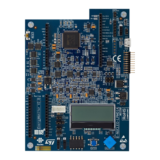
Figure 1. X-NUCLEO-LPM01A
1. Picture is not contractual.
March 2018
UM2243 Rev 2
1/41
www.st.com
1
Advertisement
Table of Contents

Related Manuals for ST X-NUCLEO-LPM01A


Summary of Contents for ST X-NUCLEO-LPM01A
-
Page 1: Figure 1. X-Nucleo-Lpm01A
It performs consumption averaging (static measurement up to 200 mA) as well as real-time analysis (dynamic measurement up to 50 mA with 100 kHz bandwidth). The X-NUCLEO-LPM01A operates either in standalone mode (using its LCD, joystick and button to display static measurements), or in controlled mode connected to a host PC via USB (using the STM32CubeMonitor-Power software tool with its comprehensive graphical user interface). -
Page 2: Table Of Contents
Hardware layout and configuration ......10 X-NUCLEO-LPM01A layout ........11 Supplying power to the X-NUCLEO-LPM01A . - Page 3 X-NUCLEO-LPM01A ........
- Page 4 Contents UM2243 Reference documents ........39 Revision history .
- Page 5 UM2243 List of tables List of tables Table 1. Ordering Information ............9 Table 2.
- Page 6 X-NUCLEO-LPM01A layout bottom view ........
-
Page 7: Features
UM2243 Features Features The X-NUCLEO-LPM01A expansion board has the following features: • Data acquisition and data treatment unit: STM32L496VGT6 Ultra-low-power MCU with ® ® 80 MHz/100 DMIPS Arm Cortex -M4 core, 1 Mbyte of Flash memory, 320 Kbytes of SRAM, 3x 12-bit ADC at 5 Msamples/s, 2 x comparators •... -
Page 8: Product Marking
Any consequences arising from such usage will not be at ST's charge. In no event will ST be liable for any customer usage of these engineering sample tools as reference designs or in production. -
Page 9: Software Tool And Embedded Software
Getting started with PowerShield firmware user manual ( PC software tool The X-NUCLEO-LPM01A expansion board can be controlled by a computer through a USB port. A computer driver for the USB virtual COM port (VCP) is required. The STM32 Virtual COM Port Driver (reference code: STSW-STM32102) can be downloaded from www.st.com. -
Page 10: Hardware Layout And Configuration
Hardware layout and configuration UM2243 Hardware layout and configuration The X-NUCLEO-LPM01A STM32 Nucleo expansion board is designed around the STM32L496VGT6 (100-pin in LQFP100 package). Figure 2: Hardware block diagram illustrates the connection between STM32L496 and peripherals. The Figure 3: X-NUCLEO-... -
Page 11: X-Nucleo-Lpm01A Layout
UM2243 Hardware layout and configuration X-NUCLEO-LPM01A layout Figure 3. X-NUCLEO-LPM01A layout top view 1. Picture is not contractual. UM2243 Rev 2 11/41... -
Page 12: Figure 4. X-Nucleo-Lpm01A Layout Bottom View
Hardware layout and configuration UM2243 Figure 4. X-NUCLEO-LPM01A layout bottom view 1. Picture is not contractual 12/41 UM2243 Rev 2... -
Page 13: Supplying Power To The X-Nucleo-Lpm01A
When the USB cable is connected, 5 V DC is provided by VBUS from the USB host port of the PC. At this step, only the embedded MCU of X-NUCLEO-LPM01A is supplied. A USB enumeration is performed between the embedded MCU and the host PC to negotiate 500 mA on VBUS. -
Page 14: Power Source From A Usb Charger
USB connector, CN5, regardless of whether or not USB enumeration succeed. If an abnormal current higher than 600 mA is drawn by the X-NUCLEO-LPM01A from USB connector CN5, an embedded current protection clamps the current and an LED (LD5, USB FS over-current LED) lights up until the over current is removed. -
Page 15: Power Source From An External Dc Power Supply
Figure 7. JP3 and CN7 (Ext Pwr setting) Note: The X-NUCLEO-LPM01A external voltage range has been limited to 10 V maximum to limit self-heating of the board, and so limit measurement variations. Nevertheless, a standard L7805 voltage regulator is used to convert the DC voltage from CN7 to 5 V. Thus the input voltage can be extended to 16 V without risk of damaging the board. -
Page 16: Power Source From The 5 V Pin Of The Arduino Uno Or Arduino Nano Connectors
A jumper should be inserted in the 'ARD' position of JP3 as shown in Figure 9: CN4 and CN13 +5V pin assignment. The X-NUCLEO-LPM01A is supplied by a 5 V DC source from either the Arduino Uno connector (CN4) or the Arduino Nano connector (CN13). See Figure 3: X-NUCLEO-LPM01A layout top view for the CN4 and CN13 placements. -
Page 17: Power Supply Connections Of A Target Board
Power supply connections of a target board Power supply connections of a target board The X-NUCLEO-LPM01A can power supply a target board from 1.8 V to 3.3 V and measure its consumption (current, power, energy) using one of the following connections: •... -
Page 18: Figure 10. Pins Aref And 3V3 Of Arduino Uno Connectors Cn4 And Cn3
JP4 ‘decoup’ position adds a 2.2 µF decoupling capacitance on the power output voltage (VOUT). It is recommended to keep JP4 jumper inserted most of the time to avoid X-NUCLEO-LPM01A dynamic measurement oscillation, especially when the target board has a decoupling capacitance of less than 1 µF on its input power supply path. -
Page 19: Settings For Use Of The Arduino Uno Connectors With Nucleo64 And Nucleo144 Use Cases
15.1: How to adapt an STM32L432 Nucleo-32 to power the MCU from the Arduino AREF pin. The power sources and the USB connector of the X-NUCLEO-LPM01A must first be disconnected to avoid any electrical conflict or damage. Then apply the correct X-NUCLEO-LPM01A jumper settings for JP9, JP10 and JP4,... -
Page 20: Settings For Use Of The Arduino Nano Connectors In A Nucleo32 Use Case
MCU only, so that only the MCU consumption is measured. In other words, this adaptation removes the consumption of peripherals such as ST-LINK. The power sources and the USB connector of the X-NUCLEO-LPM01A must first be disconnected to avoid any electrical conflict or damage. -
Page 21: Figure 14. Stm32 Nucleo32 Target Board Plugged Into The X-Nucleo-Lpm01A
UM2243 Power supply connections of a target board Figure 14. STM32 Nucleo32 target board plugged into the X-NUCLEO-LPM01A UM2243 Rev 2 21/41... -
Page 22: Power Supply Connections Of A Target Board With Basic
VOUT is fully loaded. The VDD output current should not exceed 500 mA. Caution: When the X-NUCLEO-LPM01A is supplied from a PC (USB host port), and VDD supplies the target board peripherals, do not exceed the 500 mA total budget allowed by the USB port. -
Page 23: Static Current Measurement Principle
UM2243 Static current measurement principle Static current measurement principle The static measurement mode allows a stable current to be measured over a wide range from 1 nA to 200 mA, with an accuracy of better than 2%.To use this mode properly, the target board current should not vary by more than 10% of its average value during measurement acquisition. -
Page 24: Dynamic Current Measurement Principle
Dynamic current measurement principle UM2243 Dynamic current measurement principle The dynamic measurement mode allows measurement of fluctuating currents from 100 nA to 50 mA with an accuracy in the range of 2%. Measurement acquisitions are performed using three 12-bit ADCs working in parallel at 3.2 Msamples/s each and with 100 kHz bandwidth on the analog circuit path. -
Page 25: Dynamic Current Block Diagram Description
17) when the common current measurement method by one shunt and without a stabilization loop is required by the system. For further details regarding dynamic current measurement data acquisition pre-processing and post-processing, please refer to the X-NUCLEO-LPM01A PowerShield firmware user manual [1]. UM2243 Rev 2... -
Page 26: Dynamic Current Measurements Special Care
Dynamic current measurement principle UM2243 10.3 Dynamic current measurements special care To guarantee the stability of the output voltage stabilization loop (see Figure 17), it is recommended to insert JP4 jumper to add additional 2.2 µF capacitor on output voltage VOUT (see Figure 2 for more details). -
Page 27: Standalone Mode Using Embedded User Interface
In standalone mode, both static and dynamic measurements are possible. Please refer to the X-NUCLEO-LPM01A PowerShield firmware user manual for details on measurement features available and use of the X-NUCLEO-LPM01A user-interface menus with the embedded firmware. Figure 18. Embedded user interfaces elements... -
Page 28: Host-Controlled Mode With A Pc
STM32CubeMonitor-Power user manual [2]. Both modes require installation of the USB VCP (Virtual COM port) driver ‘STM32 Virtual COM Port Driver’ on the PC. Please refer to the X-NUCLEO-LPM01A PowerShield firmware user manual for the driver reference. -
Page 29: Trigger Signals Between The X-Nucleo-Lpm01A
X-NUCLEO-LPM01A The trigger signal on Arduino connector alias D7 is controlled from the target board to trigger the X-NUCLEO-LPM01A for a conversion start or event trigger. Please refer to the X-NUCLEO-LPM01A PowerShield firmware user manual for a detailed description of the use of this trigger signal in standalone and controlled modes. -
Page 30: Figure 20. Arduino Uno D7 Trigger Signal From Target And Solder Bridges Sb26
Trigger signals between the X-NUCLEO-LPM01A and the target board UM2243 Figure 20. Arduino Uno D7 trigger signal from target and solder bridges SB26 Figure 21. Arduino Nano D7 trigger signal from target 30/41 UM2243 Rev 2... -
Page 31: Trigger Signal From X-Nucleo-Lpm01A To Target Board
13.2 Trigger signal from X-NUCLEO-LPM01A to target board D2 and D3 on the Arduino connector are controlled from the X-NUCLEO-LPM01A to trigger the target board for an event. For example, a programmable current threshold can be set (only in controlled mode) to trigger the D2 or D3 signal when the target board power consumption crosses this threshold. -
Page 32: Figure 24. Arduino Nano D2, D3 Trigger Signal To Target
Trigger signals between the X-NUCLEO-LPM01A and the target board UM2243 Figure 24. Arduino Nano D2, D3 trigger signal to target 32/41 UM2243 Rev 2... -
Page 33: Extension Connector Cn11
Specific daughter boards can be connected to the I2C bus and pin D8 of the Arduino connector sets of the X-NUCLEO-LPM01A using the extension connector CN11. By default, CN11 is not connected to the Arduino I2C bus and D8 because this connector has a reserved use which is not described here. -
Page 34: Extension Connector Used With Arduino Nano Connectors
Switch to select the type of daughterboard Two kinds of daughterboard can be used with CN11: ST or External. Move the slider of switches S1 and S2 to select the right mode. The position is silkscreen printed on the PCB between the two switches. -
Page 35: How To Adapt An Stm32L432 Nucleo-32/Nucleo-64
Remove jumper JP1: disconnect VDD from +3V3 power source Open SB9: T_NRST reset MCU from ST-LINK Open SB4 and SB17: MCO clock from ST-LINK to MCU (set HSI or use external crystal as MCU clock reference) Open SB2: STLINK_RX of Virtual COM port Open SB3: STLINK_TX of Virtual COM port. -
Page 36: How To Adapt An Stm32L496 Nucleo-144 To Power The Mcu From The Arduino Aref Pin
Remove jumper JP3: NRST from ST-LINK to MCU Open SB141: SWO from ST-LINK to MCU 10. Open SB109: MCO clock from ST-LINK to MCU (set HSI or use external crystal as the MCU clock reference) 11. Open SB131: STLK_RX of Virtual COM port 12. -
Page 37: Statement Of Compliance To Local Legislation
UM2243 Statement of compliance to local legislation Statement of compliance to local legislation 16.1 FCC Compliance Statement 16.1.1 Part 15.19 This device complies with Part 15 of the FCC Rules. Operation is subject to the following two conditions: (1) this device may not cause harmful interference, and (2) this device must accept any interference received, including interference that may cause undesired operation. -
Page 38: Déclaration De Conformité
Statement of compliance to local legislation UM2243 16.2.2 Déclaration de conformité Avis: Le présent appareil est conforme aux CNR d’Industrie Canada applicables aux appareils radio exempt de licence. L’exploitation est autorisée aux deux conditions suivantes: (1) l’appareil ne doit pas produire de brouillage, et (2) l’utilisateur de l’appareil doit accepter tout brouillage radioélectrique subi, même si le brouillage est susceptible d’en compromettre le fonctionnement. -
Page 39: Table 5. Reference Documents
UM2243 Reference documents Reference documents Table 5. Reference documents Reference Version Title Latest version Getting started with PowerShield firmware user manual (UM2269) STM32CubeMonitor-Power software tool for power and ultra-low-power Latest version measurements user manual (UM2202) UM2243 Rev 2 39/41... -
Page 40: Table 6. Document Revision History
Revision history UM2243 Revision history Table 6. Document revision history Date Version Changes 18-Oct-2017 Initial release Added Ordering information Updated: 7-Mar-2018 -System requirements, Product marking, Statement of compliance to local legislation Reference documents -STM32CubeMonitor-Power software tool ordering code 40/41 UM2243 Rev 2... - Page 41 ST products and/or to this document at any time without notice. Purchasers should obtain the latest relevant information on ST products before placing orders. ST products are sold pursuant to ST’s terms and conditions of sale in place at the time of order acknowledgement.
Need help?
Do you have a question about the X-NUCLEO-LPM01A and is the answer not in the manual?
Questions and answers