
Related Manuals for ST ST5-IP


Summary of Contents for ST ST5-IP
- Page 1 ST5-Q ST10-Q • • ST5-Si ST10-Si • • ST5-C ST10-C • • ST5-IP ST10-IP • • ST5-Q-NF ST10-Q-NF • • ST5-Si-NF ST10-Si-NF • • 920-0004 Rev. F 6/10/14...
-
Page 2: Table Of Contents
920-0004 Rev. F ST5/10-Si,-Q,-C, -IP Hardware manual 6/10/14 Contents Introduction....................................3 Features ....................................3 Block Diagrams ..................................4 Getting Started ..................................6 Connecting to the PC using RS-232 ............................8 Connecting the Drive to Your PC using Ethernet ........................10 Addresses, Subnets, and Ports ............................10 Option 1: Connect a Drive to Your Local Area Network ....................12 Using DCHP ................................14 Option 2: Connect a Drive Directly to Your PC ........................15 Option 3: Use Two Network Interface Cards (NICs) ......................17... -
Page 3: Introduction
920-0004 Rev. F ST5/10-Si,-Q,-C, IP Hardware manual 6/10/14 Introduction Thank you for selecting an Applied Motion Products motor control. We hope our dedication to performance, quality and economy will make your motion control project successful. If there’s anything we can do to improve our products or help you use them better, please call or fax. We’d like to hear from you. -
Page 4: Block Diagrams
Option Card X8/CCWLIM OUTPUT Y1 OUTPUT Y2 OUTPUT Y3 Option Card CANopen OUTPUT Y4 (Required on ST-C Drives only) or RS485 ANALOG IN1 (Optional on ST-Q Drives only) ANALOG IN2 RS-232 to PC/MMI *24 - 80 VDC for ST10 ST5-Q, ST5-C, ST10-Q and ST10-C... - Page 5 X8/CCWLIM OUTPUT Y1 OUTPUT Y2 OUTPUT Y3 Ethernet to Ethernet switch OUTPUT Y4 or network interface Option Card card ANALOG IN1 ANALOG IN2 not used RS-232 *24 - 80 VDC for ST10 ST5-Q-EN, ST5-Q-EE, ST5-IP-EN, ST5-IP-EE, ST10-Q-EN, ST10-Q-EE, ST10-IP-EN, ST10-IP-EE...
-
Page 6: Getting Started
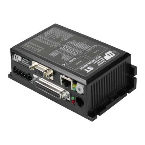
• Relevant software applications, as outlined below. All software is available as a free download from http://www.applied-motion.com/products/software. If you’ve never used an ST drive before you’ll need to get familiar with the drive and the set up software before you try to deploy the system in your application. We strongly recommend the following: 1. - Page 7 920-0004 Rev. F ST5/10-Si,-Q,-C, IP Hardware manual 6/10/14 The connectors and other points of interest are illustrated below. Depending on your drive model and appli- cation, you’ll need to make connections to various parts of the drive. These are detailed later in the manual. screw terminal HD-15 connector optional encoder feedback...
-
Page 8: Connecting To The Pc Using Rs-232
920-0004 Rev. F ST5/10-Si,-Q,-C, -IP Hardware manual 6/10/14 Connecting to the PC using RS-232 • Locate your computer within 8 feet of the drive. • If you have a CANopen drive, you still need to connect to the RS232 port on your PC to configure the drive and download Q Programs, if necessary. - Page 9 920-0004 Rev. F ST5/10-Si,-Q,-C, IP Hardware manual 6/10/14 Prolific-based USB serial adapters do not work with Windows Vista 64 or Windows 7 64 bit operating systems. For these operating systems, you will need the Byterunner USB-COMi-M or a Byterunner USB- COM-CBL.
-
Page 10: Connecting The Drive To Your Pc Using Ethernet
920-0004 Rev. F ST5/10-Si,-Q,-C, -IP Hardware manual 6/10/14 Connecting the Drive to Your PC using Ethernet This process requires three steps • Physically connect the drive to your network (or directly to the PC) • Set the drive’s IP address •... - Page 11 192.168.0.140 DHCP Settings 1 through E can be changed using the ST Configurator software (use Quick Tuner for servo drives). Setting 0 is always “10.10.10.10”, the universal recovery address. If someone were to change the other settings and not write it down or tell anyone (I’m not naming names here, but you know who I’m talking about) then you will not be able to communicate with your drive.
-
Page 12: Option 1: Connect A Drive To Your Local Area Network
920-0004 Rev. F ST5/10-Si,-Q,-C, -IP Hardware manual 6/10/14 time. Ports are used to direct traffic to the right application once it gets to the right IP address. The UDP eSCL port in our drives is 7775. To send and receive commands using TCP, use port number 7776. You’ll need to know this when you begin to write your own application. - Page 13 920-0004 Rev. F ST5/10-Si,-Q,-C, IP Hardware manual 6/10/14 Once you’ve chosen an appropriate IP address for your drive, set the rotary switch according the address table above. If none of the default addresses are acceptable for your network, you can enter a new table of IP addresses using Configurator.
-
Page 14: Using Dchp
920-0004 Rev. F ST5/10-Si,-Q,-C, -IP Hardware manual 6/10/14 manual: “Using DHCP”. 5. If the option “Use the following IP address” is selected, life is good. Change the subnet mask to “255.255.0.0” and click OK. Using DCHP If you want to use your drive on a network that where all or most of the devices use dynamic IP addresses supplied by a DHCP server, set the rotary switch to “F”. -
Page 15: Option 2: Connect A Drive Directly To Your Pc
920-0004 Rev. F ST5/10-Si,-Q,-C, IP Hardware manual 6/10/14 Option 2: Connect a Drive Directly to Your PC It doesn’t get much simpler than this: 1. Connect one end of a CAT5 Ethernet cable into the LAN card (NIC) on your PC and the other into the drive. - Page 16 920-0004 Rev. F ST5/10-Si,-Q,-C, -IP Hardware manual 6/10/14 select properties. Select “Change adapter settings” 4. You should see an icon for your network interface card (NIC). Right click and select properties. a. Scroll down until you see “Internet Properties (TCP/IP)”. Select this item and click the Properties button.
-
Page 17: Option 3: Use Two Network Interface Cards (Nics)
920-0004 Rev. F ST5/10-Si,-Q,-C, IP Hardware manual 6/10/14 NIC1 NIC2 DRIVE Option 3: Use Two Network Interface Cards (NICs) This technique allows you to keep your PC connected to your LAN, but keeps the drive off the LAN, prevent- ing possible IP conflicts or excessive traffic. 1. -
Page 18: Connecting To A Host Using Rs-485 Option Card
The ST drives can be used with either two wire or four wire RS-485 implementations. The connection can be point to point (i.e. one drive and one host) or a multi-drop network (one host and up to 32 drives). -
Page 19: Rs-232 To Rs-485 2-Wire Converter
This adjustment can be made over the network using the TD command, or it can be set using the ST Configurator software. It is not necessary to set the transmit delay in a four wire system. - Page 20 920-0004 Rev. F ST5/10-Si,-Q,-C, -IP Hardware manual 6/10/14 RS-485 Address panel appear. Just click on the address character of your choice. You can use the numer- als 0..9 or the special characters ! “ # $ % & ‘ ( ) * + , - . / : ; < = > ? @ . Just make sure that each drive on your network has a unique address.
-
Page 21: Connecting The Power Supply
Connect the motor power supply “+” terminal to the driver terminal labeled “V+”. Connect power supply “-” to the drive terminal labeled “V-”. Use 18 or 20 gauge wire. The ST drives contain an internal fuse that connects to the power supply + terminal. This fuse is not user replaceable. If you want to install a user servicable fuse in your system install a fast acting fuse in line with the + power supply lead. -
Page 22: Connecting The Motor
920-0004 Rev. F ST5/10-Si,-Q,-C, -IP Hardware manual 6/10/14 Connecting the Motor Never connect or disconnect the motor while the power is on. If you are using a non-Applied Motion Products motor, do not connect it until you have configured the drive for that motor. lead Four lead motors can only be connected one way. -
Page 23: Connecting An Encoder (Requires The Optional Encoder Feedback Card)
920-0004 Rev. F ST5/10-Si,-Q,-C, IP Hardware manual 6/10/14 Orange Orange Blk/Wht Org/Wht lead lead motor Blk/Wht motor Org/ A– A– Black Black Red/ Yellow Yel/ Yel/ Red/Wht B– B– 8 Leads Series Connected 8 Leads Parallel Connected Connecting an Encoder (Requires the optional Encoder Feedback Card) The encoder connections use a HD-15 connector, which you must connect to your encoder as shown below. -
Page 24: Interfacing To A Motion Controller
920-0004 Rev. F ST5/10-Si,-Q,-C, -IP Hardware manual 6/10/14 Interfacing to a Motion Controller In some applications, servo control is provided by a motion controller and the drive simply obeys a velocity or torque command. The industry standard for this command signal is ±10V. In most cases, the encoder signals from the motor must feed back to the controller. -
Page 25: Connecting Input Signals
ST5/10-Si,-Q,-C, IP Hardware manual 6/10/14 Connecting Input Signals The ST drives have three types of inputs: • high speed digital inputs for step & direction commands or encoder following, 5 volt logic • digital inputs for other signals, 12 - 24 volt logic •... -
Page 26: High Speed Digital Inputs
6/10/14 High Speed Digital Inputs The ST Series drives include two high speed inputs called STEP and DIR. They accept 5 volt single-ended or differential signals, up to 2 MHz. Normally these inputs connect to an external controller that provides step &... - Page 27 920-0004 Rev. F ST5/10-Si,-Q,-C, IP Hardware manual 6/10/14 X1/STEP+ X1/STEP- Master X2/DIR+ Encoder X2/DIR- Wiring for Encoder Following Using High Speed Inputs with 12-24 Volt Signals Most PLCs don’t use 5 volt logic. You can connect signal levels as high as 24 volts to the STEP and DIR inputs if you add external dropping resistors, as shown below.
- Page 28 920-0004 Rev. F ST5/10-Si,-Q,-C, -IP Hardware manual 6/10/14 +12-24V X2/DIR+ X2/DIR- with DRIVE Sinking X1/STEP+ Outputs STEP X1/STEP- Connecting to PLC with Sinking (NPN) Outputs (Most PLC’s use 24 volt logic) X2/DIR+ direction switch +24VDC X2/DIR- Power DRIVE 2200 Supply run/stop switch X1/STEP+ 2200...
- Page 29 “Common” is an electronics term for an electrical connection to a common voltage. Sometimes “common” means the same thing as “ground”, but not always. In the case of the ST drives, if you are using sourcing (PNP) input signals, then you will want to connect COM to ground (power sup- ply -).
- Page 30 Supply X3..X6 Connecting an Input to a Switch or Relay DRIVE 12-24 XCOM OUT+ X3..X6 Power Supply OUT– Connecting another Si™ drive to the ST (When output closes, input goes low). XCOM 12-24 output X3..X6 Power Proximity Supply Sensor –...
- Page 31 920-0004 Rev. F ST5/10-Si,-Q,-C, IP Hardware manual 6/10/14 12-24 output X3..X6 Proximity Power Sensor DRIVE – Supply XCOM Connecting a PNP Type Proximity Sensor to a an input (When prox sensor activates, input goes low). Connecting Limit Switches The CWLIMIT and CCWLIMIT inputs are used for connecting end of travel sensors. These inputs are differential, which allows you to use signals that are sinking (NPN), sourcing (PNP) or differen- tial (line driver).
- Page 32 You can use normally open or normally closed limit switches. Either way, wire them as shown here. Be sure to set the polarity using the Si Programmer™ for Si™ drives or the ST Configurator™ software for the ST5-Q, ST10-Q, ST5-C and ST10-C.
-
Page 33: Connecting A Potentiometer To Analog Input 1
ST5/10-Si,-Q,-C, IP Hardware manual 6/10/14 Analog Inputs inside drive The ST drives feature two analog inputs. Each input can accept a signal range of 0 to 5 VDC, ±5 VDC, 0 to 10 VDC or ±10 VDC. Signal AIN1 Conditioning The drive can be configured to operate at a speed or position that is proportional to the analog signal. -
Page 34: Programmable Outputs
ST5/10-Si,-Q,-C, -IP Hardware manual 6/10/14 Programmable Outputs IN/OUT1 The ST drives feature four digital outputs. These outputs can be set to automically control a motor brake, to signal a fault YCOM condition, to indicate when the motor is moving or to provide an output frequency proportional to motor speed (tach signal). -
Page 35: Sourcing Output
920-0004 Rev. F ST5/10-Si,-Q,-C, IP Hardware manual 6/10/14 5-24 VDC 5-24 VDC Power Supply Power Supply – – IN/OUT1 IN/OUT1 Y1/2/3 YCOM Sourcing Output Sourcing Output Y1, Y2 or Y3 Using Y4 5-24 VDC Power Supply relay – Y1/2/3 IN/OUT1 1N4935 suppression diode YCOM Driving a Relay... -
Page 36: Choosing A Power Supply
That’s because the ST drives use switching amplifiers, converting a high voltage and low current into lower voltage and higher current. The more the power supply voltage exceeds the motor voltage, the less current you’ll need from the power supply. -
Page 37: Recommended Motors
920-0004 Rev. F ST5/10-Si,-Q,-C, IP Hardware manual 6/10/14 Recommended Motors Holding Drive Rotor Part Torque Current Setting Resistance Inductance Inertia Number oz-in kg-cm amps ohms g-cm HT��-���/��� �.� �.�� �.� �.� �.� � HT��-���/��� ��.� �.�� �.� �.� �.� �� ����-���/���... -
Page 38: Torque-Speed Curves
920-0004 Rev. F ST5/10-Si,-Q,-C, -IP Hardware manual 6/10/14 Torque-Speed Curves Note: all torque curves were measured at 20,000 steps/rev. HT11-012/212, HT11-013/213, 5014-042/842 24 VDC power supply, 20000 steps/rev 5014‐042/842 (1.2 A/phase) HT11‐013/213 (1.2 A/phase) HT11‐012/212 (1.2 A/phase) rev/sec HT17 �� VDC power supply, ����� steps/rev, all motors connected in parallel HT17-278 (2.4 A/phase) HT17-075/275 (2.0 A/phase) HT17-071/271 (2.0 A/phase) - Page 39 920-0004 Rev. F ST5/10-Si,-Q,-C, IP Hardware manual 6/10/14 HT17 �� VDC power supply, ����� steps/rev, all motors connected in parallel HT17-278 (2.4 A/phase) HT17-075/275 (2.0 A/phase) HT17-071/271 (2.0 A/phase) HT17-068/268 (1.6 A/phase) rev/sec HT23 �� VDC power supply, ����� steps/rev, all motors connected in parallel HT23-603 (6.0 A/phase) HT23-401/601 (5.0 A/phase) HT23-398/598 (5.0 A/phase)
- Page 40 920-0004 Rev. F ST5/10-Si,-Q,-C, -IP Hardware manual 6/10/14 HT23 �� VDC power supply, ����� steps/rev, all motors connected in parallel HT23-603 (6.0 A/phase) HT23-401/601 (5.0 A/phase) HT23-398/598 (5.0 A/phase) HT23-394/594 (3.4 A/phase) rev/sec HT24 �� VDC power supply, ����� steps/rev HT24-108 (4.8 A/phase) HT24-105 (4.8 A/phase) HT24-100 (3.36 A/phase)
- Page 41 920-0004 Rev. F ST5/10-Si,-Q,-C, IP Hardware manual 6/10/14 HT24 �� VDC power supply, ����� steps/rev HT24-108 (4.8 A/phase) HT24-105 (4.8 A/phase) HT24-100 (3.36 A/phase) rev/sec HT34-485/486/487 with ST10 �� VDC power supply, ����� steps/rev, all motors connected in parallel 1400 HT34-487 (10 A/phase) HT34-486 (9.7 A/phase) 1200...
- Page 42 920-0004 Rev. F ST5/10-Si,-Q,-C, -IP Hardware manual 6/10/14 HT34-485/486/487 with ST10 �� VDC power supply, ����� steps/rev, all motors connected in parallel 1400 HT34-487 (10 A/phase) HT34-486 (9.7 A/phase) 1200 HT34-485 (10 A/phase) 1000 rev/sec HT34-485/486/487 with ST10 �� VDC power supply, ����� steps/rev, all motors connected in parallel 1400 HT34-487 (10 A/phase) HT34-486 (9.7 A/phase)
- Page 43 920-0004 Rev. F ST5/10-Si,-Q,-C, IP Hardware manual 6/10/14 HT34-504/505/506 with ST10 �� VDC power supply, ����� steps/rev, all motors connected in parallel 1000 HT34-506 (6.72 A/phase) HT34-505 (7.56 A/phase) HT34-504 (7.56 A/phase) rev/sec HT34-504/505/506 with ST10 �� VDC power supply, ����� steps/rev, all motors connected in parallel 1000 HT34-506 (6.72 A/phase) HT34-505 (7.56 A/phase)
-
Page 44: Motor Heating
920-0004 Rev. F ST5/10-Si,-Q,-C, -IP Hardware manual 6/10/14 HT34-504/505/506 with ST10 �� VDC power supply, ����� steps/rev, all motors connected in parallel 1000 HT34-506 (6.72 A/phase) HT34-505 (7.56 A/phase) HT34-504 (7.56 A/phase) rev/sec Motor Heating Step motors convert electrical power from the driver into mechanical power to move a load. Because step motors are not perfectly efficient, some of the electrical power turns into heat on its way through the motor. - Page 45 920-0004 Rev. F ST5/10-Si,-Q,-C, IP Hardware manual 6/10/14 5014-042/-842 Max Duty Cycle vs Speed 24 VDC, 1.2A, 40°C Ambient Mounted on 4.75" x 4.75" x .25" Aluminum Plate Speed (RPS) HT11-012/212 Max Duty Cycle vs Speed 24 VDC, 1.2A, 40°C Ambient Mounted on 3.5"...
- Page 46 920-0004 Rev. F ST5/10-Si,-Q,-C, -IP Hardware manual 6/10/14 HT17-068 Max Duty cycle vs Speed HT17-068 Max Duty cycle vs Speed 48 VDC, 1.60 Amps 40 °C Ambient 24 VDC, 1.60 Amps @40°C Ambient on 4.75 x 4.75 x .25 Aluminum Plate on 4.75 x 4.75 x .25 Aluminum Plate Speed (RPS) Speed (RPS)
- Page 47 920-0004 Rev. F ST5/10-Si,-Q,-C, IP Hardware manual 6/10/14 HT23-394 Max Duty Cycle vs Speed HT23-394 Max Duty Cycle vs Speed 24 VDC, 3.4 Amps, 40°C Ambient 48 VDC, 3.4 Amps, 40°C Ambient on 6.4 x 6.4 x .25 Aluminum Plate on 6.4 x 6.4 x .25 Aluminum Plate Speed (RPS) Speed (RPS)
- Page 48 920-0004 Rev. F ST5/10-Si,-Q,-C, -IP Hardware manual 6/10/14 HT34-485 Max Duty cycle vs Speed HT34-485 Max Duty cycle vs Speed 48 VDC, 10.0 Amps 40°C Ambient 80 VDC, 10.0 Amps 40 °C Ambient on 10 x 10 x .5 Aluminum Plate on 10 x 10 x .5 Aluminum Plate Speed (RPS) Speed (RPS)
-
Page 49: Mounting The Drive
• Never put the drive where it can get wet or where metal or other electrically conductive particles can get on the circuitry. • Always provide air flow around the drive. When mouting multiple ST drives near each other, maintain at least one half inch of space between drives. -
Page 50: Technical Specifications
920-0004 Rev. F ST5/10-Si,-Q,-C, -IP Hardware manual 6/10/14 Technical Specifications Amplifier Digital MOSFET. 20 kHz PWM. ST5: 18 - 53 VDC, motor current: 0.5 to 5.0 amps/phase peak of sine ST10: 18 - 88 VDC, motor current: 0.5 to 10 amps/phase peak of sine Digital Inputs Step &... -
Page 51: Mating Connectors And Accessories
920-0004 Rev. F ST5/10-Si,-Q,-C, IP Hardware manual 6/10/14 Mating Connectors and Accessories Mating Connectors Motor/power supply: PCD P/N ELV06100, included with drive. IN/OUT1: DB-25 male. AMP P/N 5-747912-2. Shell Kit AMP P/N 5-748678-3. Included. Optional encoder feedback: HD-15 male. Norcomp P/N 180-015-102-001. Shell Kit AMP P/N 5-748678- 1. -
Page 52: Alarm Codes
Alarm Codes In the event of an error, the red and green LEDs on the main board will flash in alternating red-green patterns as shown below. The pattern repeats until the alarm is cleared. Code Error solid green no alarm, motor disabled flashing green no alarm, motor enabled 1 red, 1 green motor stall (optional encoder only) 1 red, 2 green move attempted while drive disabled...
Need help?
Do you have a question about the ST5-IP and is the answer not in the manual?
Questions and answers