Table of Contents
Advertisement
Introduction
The
STM32WB5MM-DK
Discovery kit is designed as a complete demonstration and development platform for the
STMicroelectronics
STM32W5MMG
The STM32 device is a multi-protocol wireless and ultra-low-power device embedding a powerful and ultra-low-power radio
compliant with the Bluetooth
The hardware features of the Discovery kits are available for users to develop their applications: Audio, USB, user buttons, and
®
Bluetooth
Low Energy. Extension connectors allow easy connection of an ARDUINO
An ST-LINK/V2-1 is integrated on the board, as an embedded in-circuit debugger and programmer for the STM32 MCU and the
USB Virtual COM port bridge.
Picture is not contractual.
UM2825 - Rev 1 - April 2021
For further information contact your local STMicroelectronics sales office.
module based on the Arm
®
Low Energy (BLE) SIG specification v5.2 and with IEEE 802.15.4-2011.
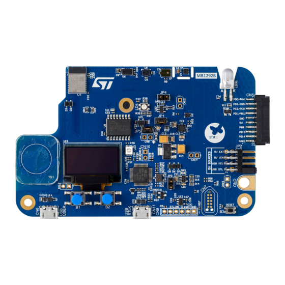
Figure 1.
STM32WB5MM-DK Discovery kit
Discovery kit with STM32WB5MMG module
®
®
®
Cortex
-M4 and Arm
Cortex
®
board for a specific application.
UM2825
User manual
®
-M0+ cores.
www.st.com
Advertisement
Table of Contents

Subscribe to Our Youtube Channel
Related Manuals for ST STM32WB5MM-DK


Summary of Contents for ST STM32WB5MM-DK
-
Page 1: Figure 1. Stm32Wb5Mm-Dk Discovery Kit
Low Energy. Extension connectors allow easy connection of an ARDUINO board for a specific application. An ST-LINK/V2-1 is integrated on the board, as an embedded in-circuit debugger and programmer for the STM32 MCU and the USB Virtual COM port bridge. -
Page 2: Features
USB user with Micro-B connector – TAG10 10-pin footprint ® • Flexible power-supply options: ST-LINK/V2-1 USB connector, 5 V delivered by ARDUINO or external connector, USB charger, or USB power • On-board ST-LINK/V2-1 debugger/programmer with USB re-enumeration capability: Virtual COM port and debug port •... -
Page 3: Ordering Information
UM2825 Ordering information Ordering information To order the STM32WB5MM-DK Discovery kit, refer to Table 1. Additional information is available from the datasheet and reference manual of the target STM32. Table 1. Ordering information Order code Board reference Target STM32 STM32WB5MM-DK... -
Page 4: Development Environment
STM32 Flash memory for easy demonstration of the device peripherals in standalone mode. The latest versions of the demonstration source code and associated documentation can be downloaded from www.st.com. UM2825 - Rev 1 page 4/42... -
Page 5: Conventions
UM2825 Conventions Conventions Table 3 provides the conventions used for the ON and OFF settings in the present document. Table 3. ON/OFF convention Convention Definition Jumper JPx ON Jumper fitted Jumper JPx OFF Jumper not fitted Jumper JPx [1-2] Jumper fitted between Pin 1 and Pin 2 Solder bridge SBx ON SBx connections closed by 0 Ω... -
Page 6: Safety Recommendations
UM2825 Safety recommendations Safety recommendations Targeted audience This product target users with at least basic electronics or embedded software development knowledge like engineer, technician, or student. This board is not a toy and is not suited for use by children. Handling the board This product contains a bare printed circuit board and as with all product of this type, the user must be careful about the following points:... -
Page 7: Quick Start
Getting started Check jumper positions on board: JP1 and JP5 ON, JP2 (Power source) on USB MCU. Install ST BLE Sensor Mobile Application on a BLE compatible mobile device from App Store or Google Play. On the host PC any freeware or commercial audio recording software can be used to interface with the Discovery board. -
Page 8: Hardware Layout And Configuration
UM2825 Hardware layout and configuration Hardware layout and configuration The STM32WB5MM-DK Discovery kit is designed around the STM32W5MMG RF module that includes an ® STM32WB55VG Bluetooth Low Energy microcontroller, a ceramic antenna, two crystals, and peripheral components. The hardware block diagram, shown in... -
Page 9: Figure 3. Stm32Wb5Mm-Dk Pcb Layout (Top View)
UM2825 Hardware layout and configuration Figure 3. STM32WB5MM-DK PCB layout (top view) Figure 4. STM32WB5MM-DK PCB layout (bottom view) UM2825 - Rev 1 page 9/42... -
Page 10: Figure 5. Stm32Wb5Mm-Dk Board Mechanical Dimensions (Top View, In Millimeters)
UM2825 Hardware layout and configuration Figure 5. STM32WB5MM-DK board mechanical dimensions (top view, in millimeters) UM2825 - Rev 1 page 10/42... -
Page 11: Embedded St-Link/V2-1
, it is not necessary to install the driver, as the ST-LINK is automatically identified. In case the STM32WB5MM-DK Discovery kit is connected to the PC before the driver is installed, some Discovery board interfaces may be declared as “Unknown” in the PC device manager. In this case, the user... -
Page 12: Power Supply
Figure 7. STM32WB5MM-DK power tree 7.2.2 7 to 12 V power supply The STM32WB5MM-DK Discovery kit can be powered with a 7 to 12 V DC power source. There are two accesses for this type of levels: ® • VIN pin of the CN2-8 ARDUINO connector. -
Page 13: Power Supply
Power supply 7.2.3 5 V power supply The STM32WB5MM-DK Discovery kit can be powered by a 5 V DC power source. The 5V signal can come from several connectors: • 5V_USB_STLK connected to CN11 (default configuration for the supply of the board). This connector is dedicated to access to the STLINK/V2 and Virtual COM port and can supply power from the host computer. -
Page 14: Current Measurement
UM2825 Power supply 7.2.4 Current measurement As the device handles low‑power features, it may be worth measuring the current consumed by the STM32W5MMG module. To easily perform this measurement, there are two possibilities: Measure the supply current of the STM32W5MMG module using an ammeter in place of the JP1 jumper. In ®... -
Page 15: Clock Sources
It uses a 32 MHz crystal oscillator. The HSE oscillator is trimmed during module manufacturing. 7.3.2 LSE clock reference The low‑speed clock (LSE) of the STM32WB5MM-DK Discovery kit is embedded on the STM32W5MMG module. It uses a 32.768 kHz crystal oscillator. Reset sources The reset signal of STM32W5MMG is active LOW. -
Page 16: Board Functions
7.5.3 Virtual COM port ST-LINK/V2-1 offers a USB Virtual COM port bridge. This feature allows access to the STM32W5MMG USART1 by the CN11 USB_STLINK connector. By default, this STM32W5MMG USART1 interface is connected to the UART2 port of the STM32F103 ST-LINK/ V2-1 MCU. -
Page 17: Leds
Board functions 7.5.5 LEDs Description Five LEDs on the top side of the STM32WB5MM-DK board help the user during the application development. Figure 10. LEDs location • LD1: this red LED indicates that the current distribution could not be performed as expected. -
Page 18: Push-Buttons
• B3 reset push‑button, used to reset STM32WB5MM-DK Discovery kit. Reset push‑button B3 is a small push‑button dedicated to the hardware reset of the STM32WB5MM-DK. It is separated from the other push‑buttons to avoid mishandling. User push‑buttons There are two push‑buttons available for the user application. They are connected to PC12 and PC13. It is possible to use them for GPIO reading or to wake up the device. -
Page 19: Embedded Sensors
UM2825 Embedded sensors Embedded sensors 7.6.1 C interface The STM32WB5MM-DK embedded sensors are connected to the STM32W5MMG module with an I C bus. The Time‑of‑Flight (ToF), accelerometer/gyroscope, and temperature sensors are connected to STM32W5MMG I2C3 bus. Table 10. STM32W5MMG I... -
Page 20: U6 Time-Of-Flight (Tof) Sensor
UM2825 Embedded sensors 7.6.2 U6 Time‑of‑Flight (ToF) sensor VL53L0CXV0DH/1 is a device that allows measuring the Time‑of‑Flight (ToF) of a laser beam. It is connected to the STM32W5MMG through the I C interface. This sensor can make a distance measurement and obstacle detection until two meters, and 1D‑gesture recognition. -
Page 21: U5 3D Accelerometer And 3D Gyroscope Sensor
UM2825 Embedded sensors 7.6.3 U5 3D accelerometer and 3D gyroscope sensor U5 ISM330DHCX is connected to STM32W5MMG through the I C interface. ISM330DHCX is a system-in-package featuring a high‑performance 3D digital accelerometer and 3D digital gyroscope tailored for Industry 4.0 applications. Figure 13. -
Page 22: U4 Temperature Sensor
UM2825 Embedded sensors 7.6.4 U4 temperature sensor STTS22H is a device that measures the ambient temperature. It is connected to the STM32W5MMG through the I C interface. Table 14. U4 temperature sensor I C address Device Action Address 0b01110001 (71h) Read STTS22H 0b01110000 (70h) -
Page 23: Board Connectors
CN1, CN2, CN3, and CN4: ARDUINO UnoV3 CN11 ST-LINK/V2-1 USB Micro-B connector The main function of this connector is to connect the STM32WB5MM-DK embedded ST-LINK/V2-1 to the PC for programming and debugging purposes. It can supply the board (Refer to Section 7.2 Power supply). -
Page 24: Cn5 Stmod+ Connector
UM2825 CN5 STMod+ connector CN5 STMod+ connector The CN5 STMod+ standard connector is on the STM32WB5MM-DK board to support flexibility in small form factor application. Figure 15 shows the pinout of the STMod+ connector. Caution: Check the orientation before plugging the fan-out or extension board. An error of orientation can generate important damage on the STM32WB5MM-DK and the plugged board. -
Page 25: Table 17. Cn5 Stmod+ Connector Pinout
UM2825 CN5 STMod+ connector Table 17. CN5 STMod+ connector pinout Pin number STM32W5MMG pin Function SPI2_NSS LPUART1_CTS SPI2_MOSI (1) LPUART1_TXD SPI2_MISO (1) LPUART1_RXD SPI2_SCK PB12 LPUART1_RTS Ground Power I2C1_SCL PB15 SPI2_MOSI (2) PB14 SPI2_MISO (2) PA10 I2C1_SDA STMOD+_RESET ADC1_IN5 PA15 PWM (TIM2_CH1) Power Ground... -
Page 26: Cn7 Tag10 Tag-Connect
NRST Reset If the TAG-Connect is used, it is very important to disable the embedded ST-LINK to avoid signal conflict between this ST-LINK and the external tool. To disable the embedded ST-LINK, it is only necessary to set the STM32F103 in reset mode, with JP3 jumper ON. -
Page 27: Cn1, Cn2, Cn3, And Cn4 Arduino ® Uno V3 Connectors
UM2825 CN1, CN2, CN3, and CN4 ARDUINO® Uno V3 connectors To benefit from this connection, it is necessary to use the TC2050-IDC-NL accessory cable shown in Figure Figure 19. TC2050-IDC-NL cable ® CN1, CN2, CN3, and CN4 ARDUINO Uno V3 connectors 8.5.1 Description ®... -
Page 28: Arduino ® Operating Voltage
STM32WB5MM-DK Discovery kit. ® Furthermore, if it is necessary to supply the STM32WB5MM-DK board with the ARDUINO connector, VIN dedicated pin is available to directly supply the board. For more information on this feature, refer to Section 7.2.2 7 to 12 V power... -
Page 29: Table 19. Arduino
UM2825 CN1, CN2, CN3, and CN4 ARDUINO® Uno V3 connectors ® Table 19. ARDUINO connector pinout Connector Pin name Signal name STM32W5MMG pin Comment NC (reserved for the test) 3V3 (IOREF) IOREF 3V3 NRST NRST NRST 3.3 V Ground Ground External Supply Input (+12V) ADC1_IN4 ADC1_IN7... -
Page 30: Stm32Wb5Mm-Dk Board Information
Evaluation tools marked as “ES” or “E” are not yet qualified and therefore not ready to be used as reference design or in production. Any consequences deriving from such usage will not be at ST charge. In no event, ST will be liable for any customer usage of these engineering sample tools as reference designs or in production. -
Page 31: Appendix Astm32Wb5Mm-Dk I/O Assignment
UM2825 STM32WB5MM-DK I/O assignment Appendix A STM32WB5MM-DK I/O assignment Table 20. STM32WB5MM-DK I/O assignment Pin number Pin name Assignment on STM32WB5MM-DK ® ADC1_IN7 (ARDUINO ® SPI1_SCK (ARDUINO D13) ADC1_IN5 (STMod+ pin 13) ® ADC1_IN4 (ARDUINO SPI2_MISO (STMod+ pin 3) ®... - Page 32 UM2825 STM32WB5MM-DK I/O assignment Pin number Pin name Assignment on STM32WB5MM-DK ® GPIO (ARDUINO ® ADC1_IN13 (ARDUINO SAI1_CK2 (Digital microphone) SAI1_DI2 (Digital microphone) ® SPI1_MOSI (SPI OLED display/ ARDUINO D1/ RGB LED driver) * LPUART_CTS (STMod+ pin 1) ® ADC1_IN10 (STMod+ pin 19 and ARDUINO D10) ®...
-
Page 33: Appendix B Federal Communications Commission (Fcc)
UM2825 Federal Communications Commission (FCC) Appendix B Federal Communications Commission (FCC) Identification of products: STM32WB5MM-DK. Contains certified module from STMicroelectronics: STM32W5MMG FCC ID: YCP-STM32WB5M01 Part 15.19 This device complies with Part 15 of the FCC Rules. Operation is subject to the following two conditions: (1) this device may not cause harmful interference, and (2) this device must accept any interference received, including interference that may cause undesired operation. -
Page 34: Appendix C Innovation, Science And Economic Development (Ised) Canada
UM2825 Innovation, Science and Economic Development (ISED) Canada Compliance Statements Appendix C Innovation, Science and Economic Development (ISED) Canada Compliance Statements This radio transmitter (8976A-STM32WB5M01) has been approved by ISED Canada to operate with the antenna types listed below with the maximum permissible gain and required antenna impedance for each antenna type indicated. -
Page 35: Appendix D Radio Equipment Directive (Red) Compliance Statement
Bande de fréquence : 2400-2483.5 MHz (Bluetooth • Puissance maximale : 4 mW p.i.r.e Simplified EC compliance statement: Hereby, STMicroelectronics declares that the radio equipment type STM32WB5MM-DK is in compliance with Directive 2014/53/EU. Frequency range used in transmission and maximal radiated power in this range: ®... -
Page 36: Revision History
UM2825 Revision history Table 21. Document revision history Date Revision Changes 23-Apr-2021 Initial release. UM2825 - Rev 1 page 36/42... -
Page 37: Table Of Contents
ST-LINK/V2-1 firmware upgrade ........ - Page 38 STM32WB5MM-DK I/O assignment ........
- Page 39 UM2825 Contents List of tables ................40 List of figures.
- Page 40 STM32WB5MM-DK I/O assignment ........
- Page 41 STM32WB5MM-DK PCB layout (bottom view) ..........9 Figure 5. STM32WB5MM-DK board mechanical dimensions (top view, in millimeters) ......10 Figure 6.
- Page 42 ST’s terms and conditions of sale in place at the time of order acknowledgement. Purchasers are solely responsible for the choice, selection, and use of ST products and ST assumes no liability for application assistance or the design of Purchasers’...
Need help?
Do you have a question about the STM32WB5MM-DK and is the answer not in the manual?
Questions and answers