Table of Contents
Advertisement
Quick Links
UM3354
User manual
Camera module for STM32 boards
Introduction
The
B-CAMS-IMX
camera module provides a compelling hardware set to handle several computer vision scenarios and use
cases. It has a high-resolution IMX335LQN 5‑Mpx RGB CMOS image sensor, an ISM330DLC inertial motion unit, and a
®
VL53L5CX ToF sensor. It can be used with any STM32 boards featuring a MIPI CSI-2
interface with a 22‑pin FFC connector to
enable full-featured computer vision on STM32 microcontrollers and microprocessors easily.
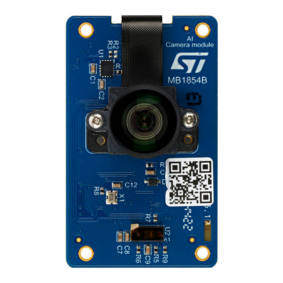
Figure 1.
B-CAMS-IMX top view without FFC
Figure 2.
B-CAMS-IMX bottom view without FFC
Pictures are not contractual.
UM3354 - Rev 1 - June 2024
www.st.com
For further information contact your local STMicroelectronics sales office.
Advertisement
Table of Contents

Related Manuals for ST B-CAMS-IMX


Summary of Contents for ST B-CAMS-IMX
-
Page 1: Figure 1. B-Cams-Imx Top View Without Ffc
VL53L5CX ToF sensor. It can be used with any STM32 boards featuring a MIPI CSI-2 interface with a 22‑pin FFC connector to enable full-featured computer vision on STM32 microcontrollers and microprocessors easily. Figure 1. B-CAMS-IMX top view without FFC Figure 2. B-CAMS-IMX bottom view without FFC Pictures are not contractual. -
Page 2: Features
UM3354 Features Features • Camera module accessory board (MB1854) including: ® – Dual-lane MIPI CSI-2 data output supporting Sony IMX335LQN 5‑Mpx RGB CMOS image sensor – M12 × 0.5 lens holder for a variety of commercially available, ready‑to‑use M12 lenses –... -
Page 3: Ordering Information
UM3354 Ordering information Ordering information To order the B-CAMS-IMX camera module, refer to Table 1. Additional information is available from the datasheet and reference manual of the target STM32. Table 1. List of available products Order code Board reference Target STM32 boards •... -
Page 4: Laser Safety Consideration
UM3354 Laser safety consideration Laser safety consideration The Time‑of‑Flight and gesture-detection sensor contains a laser emitter and the corresponding drive circuitry. The laser output is designed to remain within Class 1 laser safety limits under all reasonably foreseeable conditions including single faults in compliance with IEC 60825-1:2014 (third edition). The laser output remains within Class 1 limits as long as the STMicroelectronics recommended device settings are used and the operating conditions specified in the datasheets are respected. -
Page 5: Quick Start Guide
STM32 board. • Evaluate computer vision possibilities on STM32 devices and develop your application. • The lens is interchangeable. B-CAMS-IMX accepts the various M12‑mount lenses available on the market. UM3354 - Rev 1 page 5/20... -
Page 6: Hardware Layout And Configuration
Hardware layout and configuration Hardware layout and configuration Hardware block diagram The B-CAMS-IMX camera module is designed around the IMX335LQN 5‑Mpx RGB CMOS image sensor, an inertial motion unit (IMU), and a Time‑of‑Flight (ToF) sensor. The hardware block diagram is illustrated on Figure Figure 6. -
Page 7: Hardware Board Layout
UM3354 Hardware layout and configuration Hardware board layout Figure 7 Figure 8 help users locate these features on the B-CAMS-IMX board. Figure 7. B-CAMS-IMX PCB layout (top view) Inertial motion unit (U1) MB1854 5-Mpx IMX335LQN image sensor with M12 lens... -
Page 8: Figure 8. B-Cams-Imx Pcb Layout (Bottom View)
UM3354 Hardware layout and configuration Figure 8. B-CAMS-IMX PCB layout (bottom view) Image sensor connector (CN2) 22-pin connector (supports the FFC to the target STM32 board) (CN1) UM3354 - Rev 1 page 8/20... -
Page 9: Mechanical Drawing
UM3354 Hardware layout and configuration Mechanical drawing All measurements are in millimeters. Figure 9. B-CAMS-IMX board mechanical dimensions (bottom view, in millimeters) UM3354 - Rev 1 page 9/20... -
Page 10: Figure 10. Dimensions Of M12-Mount Lens (In Millimeters)
UM3354 Hardware layout and configuration Figure 10. Dimensions of M12‑mount lens (in millimeters) UM3354 - Rev 1 page 10/20... -
Page 11: Ffc Connector To The Target Stm32 Board
FFC connector to the target STM32 board This is the 22‑pin connector supporting the FFC connected to the target STM32 board, 3V3 signaling. 22 pins are necessary to connect all the needed signals to get the full features of B-CAMS-IMX, as described in Table Table 3. -
Page 12: Board Functions
Hardware board layout Figure 7 Figure B-CAMS-IMX top and bottom layout views. 5-Mpx IMX335LQN image sensor The camera module (HW10) is equipped with a high-resolution 5‑Mpx IMX335LQN (type 1/2.8) CMOS RGB image sensor compatible with a M12‑mounted lens. The module is provided with the following M12 lens: 1/2.8”, EFL 3.24 mm, F/NO 2.7, view angle 87°. -
Page 13: Federal Communications Commission (Fcc) And Ised Canada Compliance
Federal Communications Commission (FCC) and ISED Canada Compliance Statements FCC Compliance Statement Identification of products: B-CAMS-IMX Part 15.19 This device complies with Part 15 of the FCC Rules. Operation is subject to the following two conditions: (1) this device may not cause harmful interference, and (2) this device must accept any interference received, including interference that may cause undesired operation. -
Page 14: Ised Compliance Statement
(uncontrolled exposure). This device must not be collocated or operating in conjunction with any other antenna or transmitter. Identification of products: B-CAMS-IMX Identification du produit : B-CAMS-IMX Compliance Statement Notice: This device complies with ISED Canada licence-exempt RSS standard(s). Operation is subject to the following two conditions: (1) this device may not cause interference, and (2) this device must accept any interference, including interference that may cause undesired operation of the device. -
Page 15: Ce Conformity
Simplified declaration of conformity Hereby, STMicroelectronics declares that the radio equipment type B-CAMS-IMX is in compliance with Directive 2014/53/EU. The full text of the EU declaration of conformity is available on demand. UM3354 - Rev 1... -
Page 16: Revision History
UM3354 Revision history Table 4. Document revision history Date Revision Changes 25-Jun-2024 Initial release. UM3354 - Rev 1 page 16/20... -
Page 17: Table Of Contents
UM3354 Contents Contents Features................2 Ordering information . -
Page 18: List Of Tables
UM3354 List of tables List of tables Table 1. List of available products............. . . 3 Table 2. -
Page 19: List Of Figures
Figure 9. B-CAMS-IMX board mechanical dimensions (bottom view, in millimeters)......9 Figure 10. - Page 20 ST’s terms and conditions of sale in place at the time of order acknowledgment. Purchasers are solely responsible for the choice, selection, and use of ST products and ST assumes no liability for application assistance or the design of purchasers’...
Need help?
Do you have a question about the B-CAMS-IMX and is the answer not in the manual?
Questions and answers