Table of Contents
Advertisement
UM2510
User manual
A guide to using the VL53L1X ultra lite driver
Introduction
The purpose of this user manual is to describe the main functions of the VL53L1X ultra lite driver (ULD) to program the
VL53L1X sensor for ranging distances and detecting objects.
The VL53L1X ULD is an optimized version of the initial VL53L1X driver. The table below indicates the main differences between
the two drivers. For example, in the the VL53L1X ULD, the API contains only four files instead of 35, and the code footprint is
much smaller (2.3 KB vs. 9 KB in Flash).
The VL53L1X is the third generation of long distance ranging, Time-of-Flight sensors. Please refer to the VL53L1X datasheet for
more details.
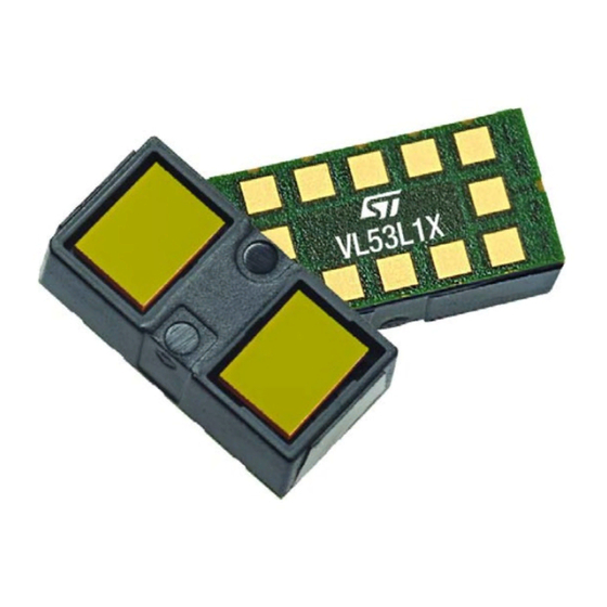
Figure 1.
VL53L1X sensor module
Table 1.
Main differences between VL53L1X API and VL53L1X ULD API
VL53L1X API
VL53L1X ULD API
Code footprint in Flash
9 KB
2.3 KB
Number of files
35
4
Timing budget (ms)
[20 - 500]
[15, 20, 33, 50, 100, 200, 500]
ROI position configuration
Flexible (center and corner)
Centered only
Fast ranging 100 Hz
Yes
No (66 Hz max.)
(1)
No
Yes
Dynamic SPAD selection (DSS)
1. DSS is an internal operation which consists of adapting dynamically the number of active SPADs according to the quantity of returned
photons. This avoids saturating the SPAD receiver. DSS is executed at the beginning of each ranging operation.
UM2510 - Rev 1 - December 2018
www.st.com
For further information contact your local STMicroelectronics sales office.
Advertisement
Table of Contents

Related Manuals for ST VL53L1X API


Summary of Contents for ST VL53L1X API
- Page 1 The VL53L1X is the third generation of long distance ranging, Time-of-Flight sensors. Please refer to the VL53L1X datasheet for more details. Figure 1. VL53L1X sensor module Table 1. Main differences between VL53L1X API and VL53L1X ULD API VL53L1X API VL53L1X ULD API Code footprint in Flash 9 KB 2.3 KB...
-
Page 2: Acronyms And Abbreviations
UM2510 Acronyms and abbreviations Acronyms and abbreviations Table 2. Acronyms and abbreviations Acronym/abbreviation Definition application programming interface counts per second dynamic SPAD selection final module test field of view inter-integrated circuit (serial bus) infrared radiation inter-measurement period kcps kilo counts per second non volatile memory region of interest SPAD... -
Page 3: Vl53L1X System Overview
(see figure below). The hardware module contains the ToF sensor. ST delivers the software driver which is referred to in this document as "the driver". This document describes the functions of the driver which are accessible to the host. These functions control the sensor and get the ranging data. -
Page 4: Ranging Api Functional Description
UM2510 Ranging API functional description Ranging API functional description This section gives a functional description of the ranging operations and describes the call flow to be followed to perform a ranging measurement using the VL53L1X sensor. Distance ranging description The sensor ranges continuously and autonomously with a programmable inter-measurement period. Autonomously means that ranging is made without involvement from the host. -
Page 5: Api Function Call Flow
UM2510 API function call flow API function call flow The VL53L1X_ULD driver is used in the following two use cases: • Calibration flow is used to calibrate the sensor. Such calibration is done during manufacturing. The calibration data must be stored in the host sytem and sent to the sensor during the bootup stage. •... -
Page 6: Mandatory Functions
UM2510 Mandatory functions 3.4.2 Ranging flow Figure 5. Ranging flow Mandatory functions Mandatory functions include: • VL53L1X_BootState • VL53L1X_SensorInit • VL53L1X_StartRanging • VL53L1X_CheckForDataReady • VL53L1X_GetDistance • VL53L1X_ClearInterrupt • VL53L1X_Stop 3.5.1 Sensor boot The VL53L1X_BootState function is used to check that the sensor has booted. It is strongly recommended to ensure that the sensor finishes booting before the first I2C access. -
Page 7: Wait For Notification Ranging Data To Be Ready
UM2510 Optional functions 3.5.4 Wait for notification ranging data to be ready There are two ways to receive notification that ranging data are ready: • The host can poll a register value change. This is done by using the VL53L1X_CheckForDataReady which returns “1”... -
Page 8: Setting Threshold And Detection Mode
UM2510 Optional functions 3.6.4 Setting threshold and detection mode In addition to the regular ranging features, the sensor also has the capability to detect a target with predefined detection criteria. When the preconfigured criteria are matched the sensor raises an interrupt and returns the distance. -
Page 9: Ranging Example Pseudo Code
UM2510 Ranging example pseudo code Ranging example pseudo code main (void ){ /* Platform Initialization code here */ /* Wait for device booted */ While(state){ Status = VL53L1X_BootState(dev, &state); HAL_delay(2); /* Sensor Initialization */ Status = VL53L1X_SensorInit() /* Modify the default configuration */ Status = VL53L1X_SetInterMeasurementPeriod();... -
Page 10: Calibration Functions
UM2510 Calibration functions Calibration functions To benefit from the full performance of the sensor, the VL53L1X_ULD driver includes two calibration functions (offset and crosstalk) which need to be run once at the production line. These calibration procedures have to be run to compensate for device-to-device variation (i.e. -
Page 11: Crosstalk Calibration Distance Characterization
UM2510 Crosstalk calibration 4.2.2 Crosstalk calibration procedure Crosstalk calibration should be conducted in a dark environment, with no IR contribution. Place a 17 % reflectance chart at the crosstalk calibration distance (xcd), then call the VL53l1X_CalibrateXtalk(dev, xcd, &xtalk) to perform the calibration. It may take a few seconds. To characterize the xcd, refer to Section 4.2.3 Crosstalk calibration distance characterization. -
Page 12: Setting Crosstalk Calibration Data
UM2510 Crosstalk calibration 4.2.5 Setting crosstalk calibration data The function VL53L1X_SetXtalk () applies the crosstalk value, in cps, to the sensor. The user may use this function to apply, to the sensor, the crosstalk correction found during calibration and stored in the host system. -
Page 13: Range Status Interpretation
UM2510 Range status interpretation Range status interpretation There are five range statuses: 0, 1, 2, 4, and 7. When the range status is 0, there is no error. Range status 1 and 2 are error warnings while range status 4 and 7 are errors. When the range status is 1, there is a sigma failure. -
Page 14: Reducing The Driver Size To Its Absolute Minimum
Reducing the driver size to its absolute minimum Reducing the driver size to its absolute minimum Although ST have attempted to create a small driver, it might not be small enough for some applications. To create the smallest possible driver, try the following approach: •... -
Page 15: Function Descriptions
UM2510 Function descriptions Function descriptions In the descriptions below, most functions return an error status. 0 is successful. Most values are unsigned 16-bit integers except where noted. Most ‘Set’ functions are paired with a corresponding ‘Get’ function. GetSWVersion VL53L1X_ERROR VL53L1X_GetSWVersion(VL53L1X_Version_t *pVersion); This function returns the SW driver version. -
Page 16: Stopranging
UM2510 StopRanging StopRanging VL53L1X_ERROR VL53L1X_StopRanging(VL53L1_Dev_t dev); This function stops the ranging. CheckForDataReady VL53L1X_ERROR VL53L1X_CheckForDataReady(VL53L1_Dev_t dev, uint8_t *isDataReady); This function checks if the new ranging data are available by polling the dedicated register. Data are not ready when "isDataReady == 0". Data are ready when "isDataReady==1". 7.10 SetTimingBudgetInMs VL53L1X_ERROR VL53L1X_SetTimingBudgetInMs(VL53L1_Dev_t dev,... -
Page 17: Bootstate
UM2510 BootState 7.16 BootState VL53L1X_ERROR VL53L1X_BootState(VL53L1_Dev_t dev, uint8_t *state); This function returns the Boot state of the device (1 = booted, 0 = not booted). 7.17 GetSensorId VL53L1X_ERROR VL53L1X_GetSensorId(VL53L1_Dev_t dev, uint16_t *id); This function returns the sensor ID which must be 0xEEAC. 7.18 GetDistance VL53L1X_ERROR VL53L1X_GetDistance(VL53L1_Dev_t dev,... -
Page 18: Setoffset
UM2510 SetOffset 7.25 SetOffset VL53L1X_ERROR VL53L1X_SetOffset(VL53L1_Dev_t dev, int16_t OffsetValue); This function programs the offset correction in mm where OffsetValue = the offset correction value to program in 7.26 GetOffset VL53L1X_ERROR VL53L1X_GetOffset(VL53L1_Dev_t dev, int16_t *Offset); This function returns the programmed offset correction value in mm. 7.27 SetXtalk VL53L1X_ERROR VL53L1X_SetXtalk(VL53L1_Dev_t dev, uint16_t XtalkValue);... -
Page 19: Getdistancethresholdlow
UM2510 GetDistanceThresholdLow 7.31 GetDistanceThresholdLow VL53L1X_ERROR VL53L1X_GetDistanceThresholdLow(VL53L1_Dev_t dev, uint16_t *low); This function returns the low threshold in mm. 7.32 GetDistanceThresholdHigh VL53L1X_ERROR VL53L1X_GetDistanceThresholdHigh(VL53L1_Dev_t dev, uint16_t *high); This function returns the high threshold in mm. 7.33 SetROI VL53L1X_ERROR VL53L1X_SetROI(VL53L1_Dev_t dev, uint16_t X, uint16_t Y); This function programs the ROI, the position of which is centered about the optical center. -
Page 20: Starttemperatureupdate
UM2510 StartTemperatureUpdate 7.39 StartTemperatureUpdate VL53L1X_ERROR VL53L1X_StartTemperatureUpdate(VL53L1_Dev_t dev); This function performs the temperature calibration. If the sensor has been stopped for a long time, it is recommended to perform the temperature update prior to restarting the ranging. By default, the sensor can adequately handle any temperature change as long as it is running, but if the sensor is stopped for an extended period of time, a temperature compensation is advised. -
Page 21: Api Structure
UM2510 API structure API structure The API is composed of four files: • VL53L1X_api.c (mandatory) • VL53L1X_api.h (mandatory) • VL53L1X_calibration.c (optional) • VL53L1X_calibration.h (optional) The VL53L1X_api.c and VL53L1X_api.h files contain all the required functions to initialize the sensor, to change the default settings, to perform ranging, and to get ranging data. -
Page 22: Revision History
UM2510 Revision history Table 3. Document revision history Date Version Changes 06-Dec-2018 Initial release UM2510 - Rev 1 page 22/26... -
Page 23: Table Of Contents
UM2510 Contents Contents Acronyms and abbreviations ............2 VL53L1X system overview . - Page 24 UM2510 Contents 4.2.1 Crosstalk calibration function ..........10 4.2.2 Crosstalk calibration procedure .
- Page 25 UM2510 Contents 7.24 VL53L1X_GetRangeStatus ........... . . 17 7.25 SetOffset .
- Page 26 ST’s terms and conditions of sale in place at the time of order acknowledgement. Purchasers are solely responsible for the choice, selection, and use of ST products and ST assumes no liability for application assistance or the design of Purchasers’...
Need help?
Do you have a question about the VL53L1X API and is the answer not in the manual?
Questions and answers