Table of Contents
Advertisement
Quick Links
Advertisement
Table of Contents

Related Manuals for Aplisens PMS-970P


Summary of Contents for Aplisens PMS-970P
- Page 1 IO.PMS-970P Revision 01.B.001 JULY 2024 USER’S MANUAL Programmable Meter PMS-970P Firmware: od v.5.00 APLISENS S.A., 03-192 Warszawa, ul. Morelowa 7 tel. +48 22 814 07 77; fax +48 22 814 07 78 www.aplisens.pl, e-mail: aplisens@aplisens.pl...
- Page 2 − excess temperature fluctuation; − steam condensation, dusting, icing. Changes made to the production may be introduced before the paper version of the user’s manual is updated. The up-to-date user’s manual is available on the manufacturer's website: www.aplisens.pl...
-
Page 3: Table Of Contents
PL.IO.PMS-970P TABLE OF CONTENST INTRODUCTION ......................4 SAFETY ........................4 LIST TO CHECK COMPLETENESS OF DELIVERY ........... 4 TRANSPORT AND STORAGE ..................4 4.1. Transport ..........................4 4.2. Storage ..........................4 WARRANTY ......................... 4 CONSTRUCTION ......................5 INSTALLATION ......................5 CONNECTING ...................... -
Page 4: Introduction
PL.IO.PMS-970T INTRODUCTION The subject of this instruction manual is the PMS-970P programmable meter. The manual includes data, hints, and recommended action for installation and usage of the meter, as well as troubleshooting tips. SAFETY − The installation and start-up of the device and any activities related to operation shall be carried out after thorough examination of the contents of user’s manual... -
Page 5: Construction
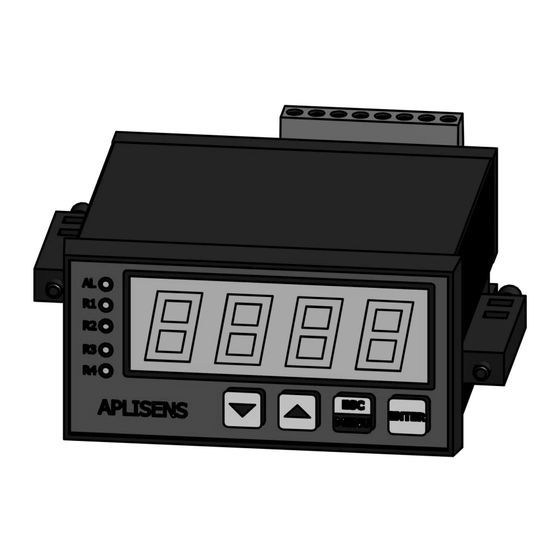
PL.IO.PMS-970P CONSTRUCTION The PMS-970P meter has two measuring inputs – one 0-20 mA current input and one 0-10 V voltage input. The current input is equipped with a safety device that protects the measuring resistor from damage. The input current is limited to 40 mA (typically). When the temperature of the measuring resistor falls, the safety device will automatically switch off and the system displays the measurement value again. - Page 6 PL.IO.PMS-970T Figure 1. Recommended installation dimensions Figure 2. Acceptable installation dimensions Figure 3. Fixing with holders 01.B.001...
-
Page 7: Connecting
PL.IO.PMS-970P Figure 4. Installation of several devices CONNECTING All connection and installation steps must be performed with power disconnected. 8.1. Safety precautions Installation should be conducted by qualified personnel, authorized to install electrical devices. All available safety requirements must be considered during installation. It is the installer’s duty to per- form installation according to this instruction manual as well as laws and standards of safety and elec- tromagnetic compatibility, relevant to the type of installation performed. - Page 8 PL.IO.PMS-970T Due to possible significant interference occurring in industrial systems, use adequate precau- tions that ensure proper operation of the device. Disregarding the following tips may, in cer- tain circumstances, lead to exceeding the levels of electromagnetic disturbance for a typical industrial environment, which in turn may cause incorrect readout on the device.
- Page 9 PL.IO.PMS-970P Figure 7. Description of terminals for version with additional passive current output Figure 8. Connection of 2-lead current transmitters Figure 9. Connection of 3-lead current transmitters 01.B.001...
- Page 10 PL.IO.PMS-970T Figure 10. Connection of voltage transmitters Figure 11. Connection of passive current output Figure 12. Connection of power supply and 4 transmitters operating loads 01.B.001...
- Page 11 PL.IO.PMS-970P Figure 13. Connection of power supply and 2 transmitters operating loads Transmitter output contacts are not equipped with quench circuit. When using transmitter outputs for switching inductive loads (contactor coils, transmitters, electromagnets, sole- noids, etc.) it is required to use an additional quench circuit (typically a 47nF condenser/ min.
-
Page 12: Table 1. Assignment Of Terminal
PL.IO.PMS-970T Table 1. Assignment of terminal Connector Symbol Terminal description Rating number POWER SUPPLY supply 230V/50Hz 230VAC POWER SUPPLY supply 24V AC/DC 24VDC (optional) excitation output 24VDC SIGNAL INPUT, EXCITATION OUT- signal ground current input 20mA voltage input 4-20mA analog output 4-20mA ANALOG OUTPUT, SERIAL... -
Page 13: Technical Parameters
PL.IO.PMS-970P TECHNICAL PARAMETERS Table 2. Technical parameters CATEGORY PARAMETER VALUE COMMENTS Accuracy +/-0.1% FS +/- 100ppm / °C Temperature coefficient Internal resolution 15 bit INPUT Sampling rate 16,6Hz Filter time constant 0-15,36s Noise rejection >65dB f=50Hz 0…21mA Range 0..20mA <56Ω... -
Page 14: Operation
PL.IO.PMS-970T Power supply – other circuits 2300VAC ELECTRIC Relay outputs – other circuits 2300VAC ISOLATION Analog output – signal input 1000VAC Dimension 48x96x120mm Weight 280g Panel cut-out 44.5x91mm MECHANICAL Panel thickness 0..15mm Horizontal spacing >70mm axis to axis Vertical spacing >120mm axis to axis Electrical safety... -
Page 15: Table 3. Button Function In Programming Mode
PL.IO.PMS-970P Table 3. Button function in programming mode Use cursor buttons to navigate through the functions and ENT button to enter selected function. Nu- merical values should be set digit by digit. Flashing digit should be adjusted using cursor buttons and stored with ENT button. -
Page 16: Table 4. Programming Menu
PL.IO.PMS-970T Table 3. Button function in programming mode Button Description scrolling up through menu functions and options ▲ increasing numerical values scrolling down through menu functions and options ▼ decreasing numerical values ESCAPE go to previous menu level ENTER, access to function selected value/option confirmation Table 4. -
Page 17: Set Point Programming
PL.IO.PMS-970P Table 5. Meter’s programming example Parameter Set value Menu function Settings Input type current Fn00 Scaling points number Fn01 Input range 4-20mA P01 : 04.00 : 0000 Fn02 P02 : 20.00 : 3000 Display range 0-3000 Decimal point position 000.0... -
Page 18: Alternate Output Control
10.5. Serial communication PMS-970P has serial communication option with RS-485 internal module installed. The meter works with Modbus RTU protocol as slave device. Function 3 (register read) and function 16 (multiple registers write). The data exchanged with the me- ter are variable type “V”... - Page 19 PL.IO.PMS-970P Variables and parameters are grouped for simplicity and functionality: Group Register range Description digital read-out, decimal point position, general status, set-point sta- 400002-400003 400004-400008 set-point values, output current 400009-400015 bargraph read-out 400033-400084 programming menu settings without serial port settings...
-
Page 20: Table 7. Modbus Register Assignment
PL.IO.PMS-970T Table 7. Modbus register assignment Register Variable/ Default number/ Type Value range Comments Parameter value Address 400002/ -999 - 9999 Digital read-out Z (R) 0x0001 (0xFC19-0x270F) bit0 (LSB): PP=1 – manual pro- gramming in progress bit1: EAL=1 - set-point program- ming in progress bit2: WEE=1 - memory write in progress... - Page 21 PL.IO.PMS-970P 0 – 9 400038/ Filtering level P (R/W) 2 (0x0002) Fn05 0x0025 (0x0000 - 0x0009) 1 (0x0001) single 400039/ Bargraph P (R/W) colour 3 (0x0003) Fn06 0x0026 colour mode 3 (0x0003) tricolour 0x0000 - H 400040/ Al 1 mode...
-
Page 22: Display Test
10.6. Display test PMS-970P has special test procedure for LED display, relays and version check. The test is initiated when the meter is powered-up with key pressed. LED segments are lighted-up in following cycle: − four digit meter version code, −... -
Page 23: Historia Modyfikacji
10000 05.2005 ModbusFirmwareID register added 01.B.001 07.2024 User Manual only for PMS-970P version INSPECTION 12.1. Periodical inspection Periodical inspection must be conducted according to standards in force. While inspecting, check the condition of electrical connections on clamps (firmness of connections) and the stability of meter fix- ing.
Need help?
Do you have a question about the PMS-970P and is the answer not in the manual?
Questions and answers