
Related Manuals for Aplisens PEM-1000


Summary of Contents for Aplisens PEM-1000
- Page 1 IO.PEM-1000(ENG) 02.A.003 MARCH 2018 USER’S MANUAL ELECTROMAGNETIC FLOWMETER PEM-1000 APLISENS S.A., 03-192 Warszawa, ul. Morelowa 7 tel. +48 22 814 07 77; fax +48 22 814 07 78 www.aplisens.pl, e-mail: aplisens@aplisens.pl...
- Page 2 Danger of mechanical impacts, excessive shocks and vibrations. Excessive temperature variations. Vapour condensation, dust, icing. Changes in product manufacture may precede an update to the user's paper documentation. Up-to-date operating manuals can be found on manufacturer's website at www.aplisens.com...
-
Page 3: Table Of Contents
IO.PEM-1000(ENG) TABLE OF CONTENTS 1. INTRODUCTION ..................6 2. SAFETY ....................... 6 3. COMPLETENESS LIST ................6 4. TRANSPORT AND STORAGE ..............7 4.1. Transport ........................7 4.2. Storage ........................7 5. WARRANTY ....................7 6. DESIGN ....................... 7 6.1. Intended use and properties ..................7 6.2. - Page 4 Figure 14 Manner of connection of the protective earth for the flow meter......25 Figure 15 Manner of driving the line of the earthing functional in the PEM-1000 flow meter. 26 Figure 16 Manner of connection of the earthing functional for the converter housing... 27 Figure 17 Manner of connection of the earthing functional for the sensor housing.
- Page 5 Table 2. Mechanical data of the sensor – PN 25 ..............12 Table 3. Mechanical data of the sensor – PN 40 ..............13 Table 4. Standard measuring ranges for the PEM-1000 flowmeter........32 Table 5. Volumetric flow as a function of linear velocity of the medium ......... 33 Table 6.
-
Page 6: Introduction
The manual contains data, guidelines and recommendations concerning installing and operating, as well as procedure in the event of a failure. The description of device configuration can be found in the IK.PEM-1000(ENG) configuration manual, and the Modbus communication is described in the IM.PEM-1000(ENG). They are available on the manufacturer's website www.aplisens.com... -
Page 7: Transport And Storage
DESIGN 6.1. Intended use and properties The PEM-1000 electromagnetic flow meter is a precise device for measuring flow of conducting liquids within pipeline installations. The electromagnetic flow meter converter is intended to work only with the sensor with which it was provided. -
Page 8: The Operating Principle
IO.PEM-1000(ENG) water management, the measurements of drinking water and wastewater, the chemical, textile, paper industries as well as mining, the food industry, energy and heating installations, agriculture. The converter processes the measuring signal from the measuring sensor into the 4...20 [mA] signal and Modbus RTU/RS 485. -
Page 9: Design And Dimensions
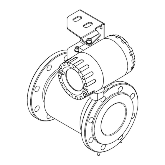
6.3. Design and dimensions The electromagnetic flow meter PEM-1000 comprises the converter and the measuring sensor. In the compact version the converter placed in the aluminum housing is embedded directly on the sensor. In the remote version the converter is mounted using the assembly equipment to the pipe or flat surface. -
Page 10: The Sensor Design
IO.PEM-1000(ENG) Figure 2. The flow meter PEM-1000NW. The remote version. 6.3.1. The sensor design The housing of the sensor is made of non-magnetic material, welded with flanges and fasteners. The insulating insert of the required properties is installed inside the pipe (compatible with the medium type). -
Page 11: Figure 3. The Flow Meter Sensor. Overall Dimensions
IO.PEM-1000(ENG) Figure 3. The flow meter sensor. Overall dimensions Mechanical data of the sensor PN16 Dimensions [mm] Weight or 200 1050 1025 1145 1125 1050 1000 1000 1285 1255 1170 Table 1. Mechanical data of the sensor – PN 16... -
Page 12: Table 2. Mechanical Data Of The Sensor - Pn 25
IO.PEM-1000(ENG) Mechanical data of the PN 25 sensor Dimensions [mm] Weight or 200 1050 1085 1145 1185 1090 1000 1000 1285 1320 1210 Table 2. Mechanical data of the sensor – PN 25 Mechanical data of the PN 40 sensor... -
Page 13: Electrodes
IO.PEM-1000(ENG) Table 3. Mechanical data of the sensor – PN 40 6.3.2. Electrodes The material of the flow meter electrodes should be matched according to its chemical resistance to the liquid in which the electrodes are immersed. The cleanliness of the electrodes may affect the precision of the measurement, and the accumulation of the impurities may have impact on the measurement process (isolation form the liquid). -
Page 14: The Converter Design
The unscrewing of the cover located opposite to the glass pane secures the access to the connecting terminals (see: p.8.1). Figure 4. Converter of the flow meter PEM-1000 with the mounting bracket. Overall dimensions Figure 5. Mounting bracket. Overall dimensions... -
Page 15: Identification Markings
IO.PEM-1000(ENG) 6.4. Identification markings Each converter is equipped with the rating plate containing the following data: 1. Logotype or name of the manufacturer; 2. The marking of the flow meter; 3. Product code; 4. CE Marking; 5. Serial number; 6. Maximum flow – Qmax;... -
Page 16: Assembly
IO.PEM-1000(ENG) ASSEMBLY 7.1. General recommendations Sensor of the electromagnetic flowmeter can be installed in any position in accordance with the requirements but in case of vertical installation axis of the electrodes should be always horizontal. Entire space inside the sensor should be filled with the measured liquid during the measurements. -
Page 17: Recommended Assembly Method For The Sensor
IO.PEM-1000(ENG) 7.2. Recommended assembly method for the sensor No liquid Air bubbles are collected in the sensor The recommended location near Recommended the riser shaft location Free outflow- zero flow (no water) sensor If vertical pipeline longer than 5m With the level decrease >5m the... -
Page 18: Assembly Of The Compact Version Of The Converter
IO.PEM-1000(ENG) 7.3. Assembly of the compact version of the converter Figure 7. Assembly of the flow meter PEM-1000ALW – examples. 02.A.003... -
Page 19: Assembly Of The Remote Version Of The Flow Meter
IO.PEM-1000(ENG) 7.4. Assembly of the remote version of the flow meter Figure 8. Assembly of the flow meter PEM-1000NW – examples 02.A.003... -
Page 20: Connection
The signal cable plug of the sensor Power cable 230V (or 10-36V DC as an option) Output cable Cable 4…20mA signal from the sensor Figure 9 Stub-ups of electrical cables from the converter of the flow meter PEM-1000. 02.A.003... -
Page 21: Electrical Connection Of The Flow Meter
RS 485 B galvanically isolated Communication RS 485 ground should be connected ground/screen any polarity Passive binary input galvanically isolated any polarity Binary output 2 galvanically isolated passive Figure 10. Marking and descriptions of connecting PINs of the flowmeter PEM-1000. 02.A.003... -
Page 22: Power Cable
IO.PEM-1000(ENG) For security reasons the power supply and output cables must be carried to the inside of the housing through separate cable glands. Cords (links) attached to screw terminals must be ended with sleeve tips of 0,75 mm When connecting the flow meter to the power supply the following rules must be observed: ... - Page 23 IO.PEM-1000(ENG) 8.2. Connection of the signal cable to the sensor The values of the signals transmitted from the electrode system of the sensor to the flow meter are at the level of millivolts. These signals are extremely sensitive to magnetic and electrostatic disturbances which are generated by the adjacent high-voltage cables, energy cables or power supply lines feeding the high power electrical devices.
-
Page 24: Figure 12 Marking Of The Stub-Ups Of The Sensor Cable Conductors
IO.PEM-1000(ENG) Figure 12 Marking of the stub-ups of the sensor cable conductors Figure 13 Connecting PINs of the sensor cable plug 02.A.003... -
Page 25: Earthing
IO.PEM-1000(ENG) 8.3. Earthing The device must be earthed in accordance with the rules existing at the place of installation. The relevant earthing terminals are placed on the housings of the sensor and the converter. 8.3.1. Protective earth The protective terminal is located in the switching chamber of the converter housing. Cable connection is shown in the figure 14. -
Page 26: Functional Earthing
Earthing of the sensor mounted on the pipeline; earthing cables have sizes of DN 10DN 40 sensor been marked in black mounted on plastic pipelines. Figure 15 Manner of driving the line of the earthing functional in the PEM-1000 flow meter. 02.A.003... -
Page 27: Figure 16 Manner Of Connection Of The Earthing Functional For The Converter Housing
IO.PEM-1000(ENG) Figure 16 Manner of connection of the earthing functional for the converter housing. The sequence of elements in the properly provided connection of the converter earthing (on fig. from the top): 1. M5 screw 2. Spring washer M5 3. Tooth washer acc. to DIN 6797 J-M5 4. -
Page 28: Start-Up
After short flushing switch the system - switch on - switch off - switch on and start measurement. Description of device configuration can be found in the IK.PEM-1000(ENG) manual, while the description of Modbus communication in the IM.PEM-1000(ENG) manual. -
Page 29: Technical Parameters
IO.PEM-1000(ENG) 10.3. Technical parameters 10.3.1. Technical specification of the sensor Nominal diameters DN 101000 Double shielded conductor e.g. Paar Tronic CY-CY 2x2x0.25mm2 lub 2x2x0.34mm2 (Helukabel) Unitronic CY PIDY 2x2x0.25mm2 or 2x2x0.34mm2 (Lapp Kabel) Connecting cables to or equivalent. the converter Length of cable: 0.5m - ALW version... -
Page 30: Technical Specifications Of The Converter
IO.PEM-1000(ENG) 10.3.2. Technical specifications of the converter 5S/cm, Minimum conductance of 20 S/cm for demineralized water the medium 0.5% value indications in the range from 20% Qmax (inclusive) to 100% Qmax Precision of the 1% value indications in the range from 10% Qmax (inclusive) -
Page 31: Reference Conditions
Standard measuring ranges PEM-1000 flowmeters are available in the size ranges of flange connections specified by the DIN standard within the range DN10 ÷ DN1000 or optionally can be executed in the size range of flange connections in accordance to the ANSI, BS standard. -
Page 32: Table 4. Standard Measuring Ranges For The Pem-1000 Flowmeter
3.54 41.667 3.40 55.556 3.14 100.000 3.18 138.889 2.83 211.111 2.99 1000 277.778 2.89 1300 361.111 2.87 2000 555.556 2.83 3000 833.333 2.95 5000 1388.889 2.76 1000 8000 2222.222 2.83 Table 4. Standard measuring ranges for the PEM-1000 flowmeter. 02.A.003... -
Page 33: Table Of Volumetric Flows Calculated For The Characteristic Flow Velocities Of The Medium For The Versions With Flanges According To Din
IO.PEM-1000(ENG) 10.5.2. Table of volumetric flows calculated for the characteristic flow velocities of the medium for the versions with flanges according to DIN. Volumetric flow is calculated based on measured linear velocity of the flow and geometry of cross-section of the flowmeter. The table presents values of the volumetric flows for the given DN for characteristic linear velocities of the flow. -
Page 34: Table 6. Values Of Flows Corresponding To The Velocity 1 M/S
IO.PEM-1000(ENG) Values of flows corresponding to the velocity 1 m/s l / min. l / s 0.283 4.712 0.079 0.637 10.62 0.177 1.131 18.85 0.314 1.767 29.452 0.491 2.895 48.255 0.804 4.524 75.398 1.257 7.069 117.81 1.964 11.946 199.1 3.318 18.096... -
Page 35: Available Pressure Ranges Acc. To Din, Ansi For Operation Of The Flowmeters For The Individual Versions For Dn Flanged Connections
IO.PEM-1000(ENG) 10.5.3. Available pressure ranges acc. to DIN, ANSI for operation of the flowmeters for the individual versions for DN flanged connections DIN PN16 DIN PN25 DIN PN40 ANSI150Ib ANSI 300Ib DN10 DN10 DN10 DN10 DN10 DN15 DN15 DN15 DN15... -
Page 36: Allowable Ambient And Operation Parameters
IO.PEM-1000(ENG) Measuring range of the flowmeter determined by Qmax parameter The manufacturer ensures maintaining of declared accuracy class in the range from 10% to 100% Qmax. If it is necessary to adapt the flowmeter to linear velocity Vn>3m/s you should contact with the manufacturer of the flowmeter. -
Page 37: Electromagnetic Compatibility, Immunity
IO.PEM-1000(ENG) 10.6.1. Electromagnetic compatibility, immunity Assessment acc. to PN-EN 61326-1, 2 for industrial applications: Electrostatic discharges (ESD): PN-EN 61000-4-2 Level S3; Contact ±6kV; Air ±8kV; Criterion B; Conducted interferences induced by fields with radio frequency: PN-EN 61000-4-6 0,15…80MHz, 10V; Criterion A;... -
Page 38: Inspections. Cleaning. Spare Parts
IO.PEM-1000(ENG) INSPECTIONS. CLEANING. SPARE PARTS 11.1. Periodic inspections Periodic inspections should be carried out in accordance with the standards valid for the user. Condition of the electrical connections on terminals (reliability of the connections) and stability of display mounting shall be checked during the inspection. - Page 39 IO.PEM-1000(ENG) 02.A.003...
Need help?
Do you have a question about the PEM-1000 and is the answer not in the manual?
Questions and answers