Table of Contents

Subscribe to Our Youtube Channel
Related Manuals for Aplisens PEM-500


Summary of Contents for Aplisens PEM-500
- Page 1 EN.IO.PEM.500 Revision 01.A.001 AUGUST 2020 USER MANUAL ELECTROMAGNETIC FLOWMETER PEM-500 APLISENS S.A., 03-192 Warsaw, Morelowa 7 St, tel. +48 22 814 07 77; fax +48 22 814 07 78 www.aplisens.com, e-mail: export@aplisens.com...
- Page 2 PRODUCT CODE – see: Flowmeter identification). The QR code or link identifies the flowmeter and provides quick access to the following documentation on the manufacturer’s website: user’s manual, MODBUS manual, configuration manual, declarations of conformity and copies of certificates. PEM-500 https://www.aplisens.pl/ID/002600110009000000000000000352/...
- Page 3 − possible mechanical impacts, excessive shocks and vibration; − excessive temperature fluctuation; − water vapour condensation, dusting, icing. Changes made to the manufacturing of products may be introduced before the paper version of the manual is updated. The up-to-date manuals are available on the manufacturer’s website: www.aplisens.com.
-
Page 4: Table Of Contents
7.1. General recommendations ....................11 7.2. Recommended assembly method for the sensor ..............11 7.3. Installation of the PEM-500 flowmeter ................. 13 8. ELECTRICAL CONNECTION ..............14 8.1. Grounding ..........................16 9. START-UP ....................17 10. TECHNICAL PARAMETERS ..............17 10.1. - Page 5 Figure 3. Overall dimensions of the sensor..................9 Figure 4. Recommended installation of the sensor................11 Figure 5. Installation of the PEM-500 flowmeter – examples............. 13 Figure 6. Example of functional earthing connection for metallic (A) piping and for insulated piping using earthing rings (B).
-
Page 6: Introduction
EN.IO.PEM.500 INTRODUCTION The user manual covers the electromagnetic flowmeter PEM-500. The manual contains data, tips and general recommendations for the safe installation and operation of the flowmeter. The description of the flowmeter configuration is given in the configuration manual ®... -
Page 7: Identification
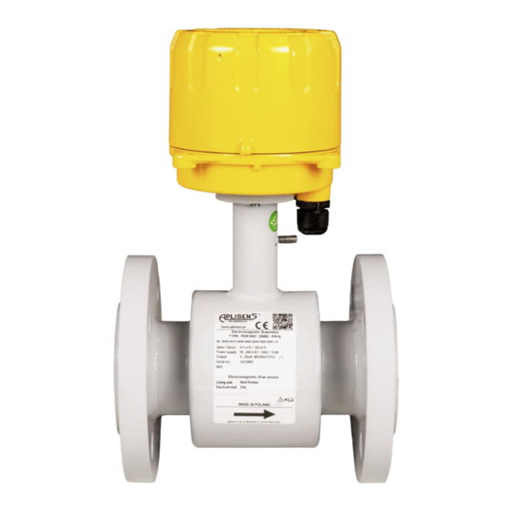
APLISENS S.A. 03-192 Warsaw Morelowa 7 St Poland 5.2. Flowmeter identification Figure 1. Nameplate of the PEM-500. 1. Logo and name of manufacturer. 10. IP rating. 2. CE mark. 11. Insulation lining material. 3. QR product code. 12. Material of electrodes. -
Page 8: Ce Mark, Declaration Of Conformity
6.1. Intended use and features The electromagnetic flowmeter PEM-500 is designed for volumetric measurement of the flow rate of conductive liquids in piping systems. It measures the flow and volume of the fluid flowing in both directions. Complete filling of the sensor tube by the fluid is required for correct measurement. -
Page 9: Table 1. Pn 16 Sensor Data
EN.IO.PEM.500 The sensor enclosure is made of non-magnetic material, welded with flanges and a set of fastenings. An insulating insert of the required properties is placed inside the tube (compatible with the type of fluid). The system of electromagnet coils generating the required magnetic field is fixed directly on the measuring tube. -
Page 10: Electrodes
EN.IO.PEM.500 Table 2. PN 25 sensor data. Dimensions [mm] Weight [kg] 150 or 200 Table 3. PN 40 sensor data. Dimensions [mm] Weight [kg] 150 or 200 6.2.1. Electrodes The material of the electrodes of the flow sensor has to be selected to correspond with its chemical resistance to the fluid in which the electrodes will be immersed. -
Page 11: Installation
EN.IO.PEM.500 INSTALLATION 7.1. General recommendations − It is recommended that the flow direction matches the direction of the arrow on the sensor; the transmitter is set by default to operate in that direction. It is possible to reverse the flow direction on the instrument in operation, but then the flow direction must also be changed in transmitter parameters. - Page 12 EN.IO.PEM.500 In order to avoid metrological errors caused by air bubbles or lining damage, the following points must be observed: during installation, the sensor must be properly positioned, the flange bolts must be tightened simultaneously on both sides; it is recommended that the flowmeter be installed so that the axis of the electrodes is ➔...
-
Page 13: Installation Of The Pem-500 Flowmeter
7.3. Installation of the PEM-500 flowmeter Figure 5. Installation of the PEM-500 flowmeter – examples. It is recommended to install the flowmeter in the horizontal (A) position (it is possible to deviate from the horizontal plane by approx. 30° (B)) and in the vertical (C) position –... -
Page 14: Electrical Connection
EN.IO.PEM.500 ELECTRICAL CONNECTION All connection and installation operations must be performed with supply voltage and other external voltages (if used) disconnected. A circuit breaker must be installed next the flowmeter transmitter (in the same room) on the flowmeter feeding line. It must be easily accessible and clearly and unambiguously marked with symbols compliant with local electrical equipment safety regulations. -
Page 15: Table 6. Marking Of Signal Conductors For The High-Voltage Version (230 V)
PL.IO.PEM.500 Table 6. Marking of signal conductors for the high-voltage version (230 V). Wire colour Wire number** Description Blue Not used in high voltage version Brown Transparent Any polarity, galvanic isolated 2-state output passive Gray Output Pink Any polarity, galvanic isolated pulse / frequency Violet passive... -
Page 16: Grounding
PL.IO.PEM.500 8.1. Grounding The flowmeter has to be earthed according to the rules applicable at the place of installation. Lack of functional earthing may cause significant disturbances of measurements. Designation of the point of connection of the functional earthing on the flowmeter. ➔... -
Page 17: Start-Up
The description of the device configuration is given in the manual EN.IK.PEM.500, whereas ® the Modbus communication is described in the manual EN.IM.PEM.500. The documentation is available on the manufacturer's website at www.aplisens.com. 10. TECHNICAL PARAMETERS 10.1. Electrical connections 10.1.1. Output signals... -
Page 18: Technical Parameters
EN.IO.PEM.500 10.3. Technical parameters 10.3.1. Technical specifications Table 7. Technical data od PEM-500 flowmeter. Technical data 5 µS/cm Minimum fluid conductivity Nominal diameters DN 10…250, (ANSI 0.5”…10”) 10 Maximum pressure Standard 1.6 MPa (2.5 MPa, 4 MPa) -
Page 19: Metrological Parameters
Metrological parameters 10.5.1. Standard measuring ranges PEM-500 flowmeters are available in the size ranges of flange connections specified by the DIN standard within the range DN10 ÷ DN250 or optionally can be executed in the size range of flange connections in accordance to the ANSI, BS standard. -
Page 20: Table 9. Volume Flow Versus Fluid Linear Velocity
EN.IO.PEM.500 10.5.2. Table od volumetric flows calculated for characteristic fluid flow velocities for flanged execution acc. to DIN. The volumetric flow is calculated from the measured linear velocity of the flow and the geometry of the flowmeter cross-section. The table shows the values of volume flow for individual DNs at characteristic linear flow speeds. -
Page 21: Available Pressure Ranges Acc. To Din, Ansi Of Flowmeters Operation For Individual Designs Of Dn Size Of Flange Connections
2 m/s during measurement. Figure 8. Recommended flow values for the PEM-500 flowmeter. Mapping of the momentary flow value with a 4…20 mA current signal is limited to the flow range determined by the parameters in accordance with Fig. -
Page 22: Permissible Ambient And Operating Parameters
EN.IO.PEM.500 Figure 9. “Outputs” tab view – setting the flow values for 4 mA and 20 mA current. “4 mA flow value” and “20 mA flow value” (with the unit identical to the one set in the “Flow unit” option in the “Basic”... -
Page 23: Maintenance
EN.IO.PEM.500 11. MAINTENANCE 11.1. Periodic inspections Periodic inspections must be carried out in accordance with applicable standards. During the inspection, check the condition of the electrical connections and the stability of the flowmeter mounting. 11.2. Non-periodic inspections If it is likely that the device at the installation location has been exposed to mechanical damage, overvoltage or improper operation has been identified, the device should be inspected.
Need help?
Do you have a question about the PEM-500 and is the answer not in the manual?
Questions and answers