
Related Manuals for Amazone Cobra 6000-2TX


Summary of Contents for Amazone Cobra 6000-2TX
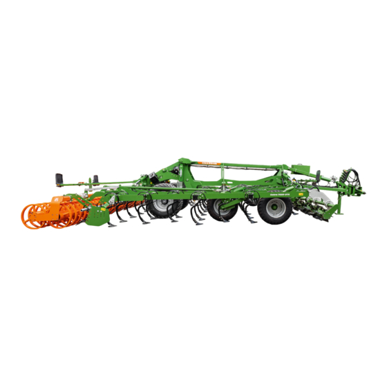
- Page 1 Original operating manual Trailed shallow cultivator Cobra 6000-2TX Cobra 7000-2TX SmartLearning www.amazone.de...
- Page 2 Please enter the identification data of the implement. The identification data can be found on the rating plate.
-
Page 3: Table Of Contents
6 Preparing the machine 4.4.2 Layout of the warning symbols Checking the tractor suitability 4.4.3 Description of the warning symbols 6.1.1 Calculating the required tractor Lighting and identification for characteristics road travel MG7478-EN-GB | G.1 | 28.06.2024 | © AMAZONE... - Page 4 Turning on the headlands 6.4.5 Moving the harrow into transport position 6.4.6 Folding the implement 8 Eliminating faults 6.4.7 Aligning the implement horizontally at transport height 9 Parking the machine Applying the parking brake MG7478-EN-GB | G.1 | 28.06.2024 | © AMAZONE...
- Page 5 10.1.10 Checking the wheels and tyres 10.1.11 Checking the hub bearing 10.1.12 Checking the brake pads 10.1.13 Checking the dual-circuit pneumatic brake system 10.1.14 Draining the compressed air tank 10.1.15 Checking the compressed air tank MG7478-EN-GB | G.1 | 28.06.2024 | © AMAZONE...
-
Page 7: About This Operating Manual
WARNING Indicates a possible threat with moderate risk for severe physical injury or death. CAUTION Indicates a threat with low risk for light or moderately severe physical injuries. MG7478-EN-GB | G.1 | 28.06.2024 | © AMAZONE... -
Page 8: Further Instructions
Example: 1. Instruction 1 2. Instruction 2 1.2.3.2 Instructions and responses CMS-T-005678-B.1 Reactions to instructions are marked with an arrow. Example: 1. Instruction 1 Reaction to instruction 1 2. Instruction 2 MG7478-EN-GB | G.1 | 28.06.2024 | © AMAZONE... - Page 9 CMS-T-00013932-B.1 WORKSHOP WORK Identifies maintenance work that must be performed at a workshop that is adequately equipped in terms of agricultural technology, safety and environmental technology by specialist personnel with appropriate training. MG7478-EN-GB | G.1 | 28.06.2024 | © AMAZONE...
-
Page 10: Lists
A list of other applicable documents can be found in the Appendix. 1.4 Digital operating manual CMS-T-00002024-B.1 The digital operating manual and e-learning can be downloaded from the Info Portal on the AMAZONE website. 1.5 Your opinion is important CMS-T-000059-D.1 AMAZONEN-WERKE H. Dreyer &... -
Page 11: Safety And Responsibility
2.1.2.1.1 Requirements for persons working with the implement CMS-T-00002310-C.1 If the implement is used improperly, people can be injured or killed: To prevent accidents due to improper use, every person who works with MG7478-EN-GB | G.1 | 28.06.2024 | © AMAZONE... - Page 12 Farmers are basically familiar with working with agricultural implements and can instruct agricultural helpers in how to use the implements if necessary. They can perform odd tasks and simple maintenance and repair work on agricultural implements themselves. MG7478-EN-GB | G.1 | 28.06.2024 | © AMAZONE...
- Page 13 Passengers can fall, be run over and severely injured or killed due to machine movements. Ejected objects can hit and injure passengers. Do not let anybody ride on the machine. Do not let anybody climb onto the driving machine. MG7478-EN-GB | G.1 | 28.06.2024 | © AMAZONE...
- Page 14 Non-observance of the technical limits values of the machine can result in accidents and serious personal injury or even death. Moreover, the machine can be damaged. The technical limit values can be found in the Technical Data. Comply with the technical limit values. MG7478-EN-GB | G.1 | 28.06.2024 | © AMAZONE...
- Page 15 Missing warning symbols increase the risk of serious and lethal personal injury. Clean dirty warning symbols. Immediately replace any damaged and illegible warning symbols. Put the intended warning symbols on spare parts. MG7478-EN-GB | G.1 | 28.06.2024 | © AMAZONE...
-
Page 16: Knowing And Preventing Dangers
If the universal joint shaft is angled down too strongly: Switch off the universal joint shaft drive. If you do not need the universal joint shaft: Switch off the universal joint shaft drive. MG7478-EN-GB | G.1 | 28.06.2024 | © AMAZONE... - Page 17 When the drives are switched off, machine parts can continue running and cause serious personal injury or death. Before approaching the machine, wait until any machine parts that are still running have come to a stop. Only touch machine parts that are standing still. MG7478-EN-GB | G.1 | 28.06.2024 | © AMAZONE...
- Page 18 If people enter the danger area, CMS-I-001131 immediately switch off the engines and drives. Before you work in the danger area of the implement, secure the tractor and implement. This also applies for quick checking work. MG7478-EN-GB | G.1 | 28.06.2024 | © AMAZONE...
-
Page 19: Safe Operation And Handling Of The Machine
Use only suitable tractors for coupling and transporting the implement. When the implement is coupled onto the tractor, make sure that the tractor's connecting device meets the implement requirements. Couple the implement properly to the tractor. MG7478-EN-GB | G.1 | 28.06.2024 | © AMAZONE... - Page 20 If the machine is not properly prepared for road travel, it can result in serious traffic accidents. Check the lighting and identification for road travel for proper function. Remove coarse dirt from the implement. Follow the instructions in the section "Preparing the implement for road travel". MG7478-EN-GB | G.1 | 28.06.2024 | © AMAZONE...
-
Page 21: Safe Maintenance And Modification
To ensure that the operating permit remains valid in accordance with national and international regulations, ensure that the specialist workshop only uses conversion parts, spare parts and special equipment approved by AMAZONE. MG7478-EN-GB | G.1 | 28.06.2024 | © AMAZONE... - Page 22 Particularly on slopes, additionally secure the machine against rolling away with wheel chocks. Remove the ignition key and carry it with you. Wait until all parts that are still running come to a stop and that hot parts cool down. MG7478-EN-GB | G.1 | 28.06.2024 | © AMAZONE...
- Page 23 Never modify safety-related components. Never drill out existing holes. Perform all maintenance work at the prescribed maintenance intervals. MG7478-EN-GB | G.1 | 28.06.2024 | © AMAZONE...
- Page 24 2.1.5.3 Operating materials CMS-T-00002324-C.1 Unsuitable operating materials Operating materials that do not meet AMAZONE requirements can cause implement damage and accidents. Only use operating material that meet the requirements in the Technical Data. MG7478-EN-GB | G.1 | 28.06.2024 | © AMAZONE...
-
Page 25: Safety Routines
CMS-T-00002325-B.1 Special equipment, accessories, and spare parts Special equipment, accessories, and spare parts that do not meet AMAZONE requirements can impede the operational safety of the implement and cause accidents. Only use original parts or parts that meet AMAZONE requirements. - Page 26 2 hands and one foot or 2 feet and one hand on the implement. When climbing up and down, never hold onto the control elements. When climbing down, never jump off of the implement. MG7478-EN-GB | G.1 | 28.06.2024 | © AMAZONE...
-
Page 27: Intended Use
AMAZONE. Uses other than those specified under the intended use are considered as improper. The manufacturer is not liable for any damage resulting from improper use, solely the operator is responsible. MG7478-EN-GB | G.1 | 28.06.2024 | © AMAZONE... -
Page 28: Product Description
14 Rear harrow 15 Side closer 16 Drag tines 17 Tine with coulter 18 Tine row 19 Support wheel 20 Cutting roller 21 Hydraulically folding sections 22 Front lighting and identification for road travel MG7478-EN-GB | G.1 | 28.06.2024 | © AMAZONE... -
Page 29: Implement Overview
Hydraulic working depth adjustment of the coulters crushboard 10 Jack on hydraulic drawbar Switch tap for traction assistance 11 Traction assistance 12 Stop tap for hydraulic drawbar 13 Drawbar eye 14 Ball hitch coupling MG7478-EN-GB | G.1 | 28.06.2024 | © AMAZONE... -
Page 30: Function Of The Implement
The roller reconsolidates the soil. The rear harrow crumbles the soil and deposits cut- off plant residues on the soil surface. The GreenDrill pack top seed drill spreads catch crops during soil tillage. MG7478-EN-GB | G.1 | 28.06.2024 | © AMAZONE... -
Page 31: Special Equipment
Preparation for working without the roller Service box Hectare counter Traction assistance GreenDrill pack top seed drill Conveyor section for the GreenDrill pack top seed drill, FTender front-mounted hopper or XTender rear-mounted hopper MG7478-EN-GB | G.1 | 28.06.2024 | © AMAZONE... -
Page 32: Warning Symbols
4.4.1 Positions of the warning symbols CMS-T-00009223-B.1 MD094 MD174 MD095 MD102 MD199 MD096 MD078 MD078 MD108 MD108 MD082 MD155 MD089 MD079 CMS-I-00006418 MD174 MD078 MD079 MD089 MD155 MD082 MD108 MD108 MD078 CMS-I-00006417 MG7478-EN-GB | G.1 | 28.06.2024 | © AMAZONE... - Page 33 4 | Product description Warning symbols MD101 MD101 CMS-I-00006416 MD273 MD155 MD273 MD155 CMS-I-00006415 MG7478-EN-GB | G.1 | 28.06.2024 | © AMAZONE...
-
Page 34: Layout Of The Warning Symbols
A warning symbol consists of two fields: Field 1 shows the following: A pictogram depicting the danger area, CMS-I-00000416 surrounded by triangular safety symbol The order number Field 2 shows a pictogram depicting how to avoid the danger. MG7478-EN-GB | G.1 | 28.06.2024 | © AMAZONE... -
Page 35: Description Of The Warning Symbols
Do not let anybody climb onto the driving implement. CMS-I-000081 MD089 Risk of crushing from the machine parts unintentionally lowering Make sure that there is nobody standing in the danger area. CMS-I-00003027 MG7478-EN-GB | G.1 | 28.06.2024 | © AMAZONE... - Page 36 Never look for leaks in hydraulic hose lines using your hand or fingers. Never attempt to plug leaks in hydraulic hose lines using your hand or fingers. If you are injured by hydraulic oil, consult a doctor immediately. CMS-I-000216 MG7478-EN-GB | G.1 | 28.06.2024 | © AMAZONE...
- Page 37 MD 108 Severe injuries due to incorrect handling of the hydraulic accumulator when it is under pressure Have the pressurised hydraulic accumulator checked and repaired only by a qualified specialist workshop. CMS-I-00004027 MG7478-EN-GB | G.1 | 28.06.2024 | © AMAZONE...
- Page 38 To do so, use the parking brake and/or wheel chocks. CMS-I-00000458 MD 199 Risk of accident if the hydraulic system pressure is too high Only couple the implement to tractors with a maximum tractor hydraulic pressure of 210 bar. CMS-I-00000486 MG7478-EN-GB | G.1 | 28.06.2024 | © AMAZONE...
-
Page 39: Lighting And Identification For Road Travel
Rear lights, brake lights, and turn indicators Reflector, yellow CMS-I-00003575 NOTE The lighting and identification for road travel can vary depending on the national regulations. 4.5.2 Front lighting and identification CMS-T-00009971-B.1 Warning signs Reflector, white CMS-I-00004522 MG7478-EN-GB | G.1 | 28.06.2024 | © AMAZONE... -
Page 40: Additional License Plate
4.5.3 Additional license plate CMS-T-00003999-C.1 Licence plate lighting Licence plate holder CMS-I-00003163 4.6 Threaded cartridge CMS-T-00001776-E.1 The threaded cartridge contains the following items: Documents Aids CMS-I-00002306 MG7478-EN-GB | G.1 | 28.06.2024 | © AMAZONE... -
Page 41: Rating Plates
4.8.1 Information about the stop tap on the hydraulic drawbar CMS-T-00004952-C.1 The figure shows that the stop tap on the hydraulic drawbar is locked in position 1 and open in position ME1677 CMS-I-00003535 MG7478-EN-GB | G.1 | 28.06.2024 | © AMAZONE... -
Page 42: Information On The Float Position Of Hydraulic Valves
The figure indicates that the traction assistance is switched on when the switch tap is in Position "1" and is switched off when the switch tap is in Position "0". ME1678 CMS-I-00008055 MG7478-EN-GB | G.1 | 28.06.2024 | © AMAZONE... -
Page 43: Soil Tillage Tools
4-8 cm 4.9.2.2 Work patterns of the coulters CMS-T-00009490-B.1 Coulter Work pattern Narrow coulter 50 mm HD narrow coulter 50 mm Duck foot coulter 220 mm HD duck foot coulter 220 mm MG7478-EN-GB | G.1 | 28.06.2024 | © AMAZONE... -
Page 44: Setting Lever For The Trailing Elements
With the setting lever, the tilt of the harrow systems, the double harrow, the spring blade system and the spring clearer system can be conveniently adjusted. Setting lever in parking position CMS-I-00002241 Setting lever in set position CMS-I-00007912 MG7478-EN-GB | G.1 | 28.06.2024 | © AMAZONE... -
Page 45: Technical Data
Category 3, Category 4N and Category K700 Ball hitch coupling M20/K80 Drawbar eye 46, 58 und 79 mm diameter Drawbar eye for hitch drawbar 50 mm diameter Ball joint drawbar eye 51 und 71 mm diameter MG7478-EN-GB | G.1 | 28.06.2024 | © AMAZONE... -
Page 46: Forward Speed
The workplace-related emission sound pressure level is lower than 70 dB(A), measured in operating condition at the ear of the tractor driver with the cab closed. The emission sound pressure level mainly depends on the vehicle used. MG7478-EN-GB | G.1 | 28.06.2024 | © AMAZONE... -
Page 47: Drivable Slope Inclination
5.8 Tyre inflation pressure and tightening torque of the wheels CMS-T-00015713-A.1 Wheel type Tyre inflation pressure Tightening torque M20x1.5 350 Nm Running gear wheel 2.8 bar M22x1.5 450 Nm Support wheel 2.8 bar M18x1.5 270 Nm MG7478-EN-GB | G.1 | 28.06.2024 | © AMAZONE... -
Page 48: Preparing The Machine
Front axle load of the operational tractor without mounted implement or ballast weights Rear axle load of the operational tractor without mounted implement or ballast weights Total weight of front-mounted implement or front ballast Drawbar load MG7478-EN-GB | G.1 | 28.06.2024 | © AMAZONE... - Page 49 × × F c T b 0,2 T b Vmin Vmin Vmin CMS-I-00003504 2. Calculate the actual front axle load. × × - × T b F c Vtat Vtat Vtat CMS-I-00005422 MG7478-EN-GB | G.1 | 28.06.2024 | © AMAZONE...
- Page 50 Tyre load according to according to capacity for two tractor operating calculation tractor tyres manual ≤ Minimum front ballasting ≤ Total weight ≤ ≤ Front axle load ≤ ≤ Rear axle load MG7478-EN-GB | G.1 | 28.06.2024 | © AMAZONE...
-
Page 51: Determining The Required Coupling Devices
Rotating drawbar eye 50 mm Non-swivel clevis coupling Rotating drawbar eye Lower link hitch Lower link traverse Check whether the coupling device of the tractor is compatible with the coupling device of the implement. MG7478-EN-GB | G.1 | 28.06.2024 | © AMAZONE... -
Page 52: Comparing The Permissible Dc Value With Actual Dc Value
6.2 Coupling the implement CMS-T-00009285-D.1 6.2.1 Removing the safety device against unauthorised use CMS-T-00005089-B.1 1. Unlock the padlock. 2. Remove the safety device against unauthorised use from the hitch device. CMS-I-00003534 MG7478-EN-GB | G.1 | 28.06.2024 | © AMAZONE... -
Page 53: Driving The Tractor Towards The Implement
Stickers are applied on the implement for the markings, which illustrate the respective hydraulic functions. The tractor control unit is used with different types of actuation, depending on the hydraulic function: CMS-I-00000121 MG7478-EN-GB | G.1 | 28.06.2024 | © AMAZONE... - Page 54 Risk of injury or even death If the hydraulic hose lines are incorrectly connected, the hydraulic functions may be faulty. When coupling the hydraulic hose lines, observe the coloured markings on the hydraulic plugs. MG7478-EN-GB | G.1 | 28.06.2024 | © AMAZONE...
-
Page 55: Coupling The Power Supply
1. Insert the plug 1 for the power supply. 2. Route the power supply cable with sufficient freedom of movement and without chafing or pinching points. 3. Check the lighting on the implement for proper function. CMS-I-00001048 MG7478-EN-GB | G.1 | 28.06.2024 | © AMAZONE... -
Page 56: Coupling The Isobus Or Control Computer
2 from the parking device. 6. Connect the red coupling head to the coupling marked in red on the tractor. 7. Route the brake lines with sufficient freedom of movement and without chafing or pinching points. MG7478-EN-GB | G.1 | 28.06.2024 | © AMAZONE... -
Page 57: Coupling On The Lower Link Hitch
2. Pull out the linch pin from the pin. 3. Pull out the pin. 4. Swivel up the jack. 5. Insert the pin. 6. Secure the pin with a linch pin. CMS-I-00003350 MG7478-EN-GB | G.1 | 28.06.2024 | © AMAZONE... -
Page 58: Coupling The Ball Hitch Coupling Or Drawbar Eye
2. Pull out the linch pin from the pin. 3. Pull out the pin. 4. Swivel up the jack. 5. Insert the pin. CMS-I-00003552 6. Secure the pin with a linch pin. MG7478-EN-GB | G.1 | 28.06.2024 | © AMAZONE... -
Page 59: Removing The Wheel Chocks
2. Fold the foldable wheel chocks. 3. Put the wheel chocks in the holder. CMS-I-00007790 6.2.11 Releasing the parking brake CMS-T-00009332-A.1 Release the parking brake 1 with the hand crank 2 . CMS-I-00006794 MG7478-EN-GB | G.1 | 28.06.2024 | © AMAZONE... -
Page 60: Preparing The Implement For Operation
6.3.1.1 Lifting implements with rigid drawbar CMS-T-00009860-A.1 Simultaneously lift the tractor lower links and, using the "yellow" tractor control unit, completely extend the piston rods 1 of the running gear hydraulic cylinder 2 . CMS-I-00006899 MG7478-EN-GB | G.1 | 28.06.2024 | © AMAZONE... -
Page 61: Unfolding The Implement
To unfold the implement: Lift the implement completely. 1. Lift the implement, see page 54. The implement will be completely lifted. MG7478-EN-GB | G.1 | 28.06.2024 | © AMAZONE... -
Page 62: Preparing The Implement For Working Without The Roller
Screw on the mount 1 for the roller holder onto the roller. 2. Insert the parking legs 3 of the roller holder into the mount. 3. Secure the parking legs with the linch pins 2 . CMS-I-00004834 MG7478-EN-GB | G.1 | 28.06.2024 | © AMAZONE... - Page 63 After swivelling in the spacer elements, make sure that the recesses of the spacer elements are always fully resting on the piston rods. MG7478-EN-GB | G.1 | 28.06.2024 | © AMAZONE...
- Page 64 Working depth scale value Number of spacer elements to be swivelled in All adjustable values 5 x 4 mm and 5 x 10 mm 12. Push the double pin all the way down again. MG7478-EN-GB | G.1 | 28.06.2024 | © AMAZONE...
-
Page 65: Preparing The Implement For Working With The Roller
After swivelling in the spacer elements, make sure that the recesses of the spacer elements are always fully resting on the piston rods. MG7478-EN-GB | G.1 | 28.06.2024 | © AMAZONE... - Page 66 B between the inner side panel of the roller frame and the inner roller mount 2 are each 65.2 cm. CMS-I-00006927 MG7478-EN-GB | G.1 | 28.06.2024 | © AMAZONE...
-
Page 67: Adjusting The Scraper To The Roller
16. Secure the parking legs with the linch pins. CMS-I-00004835 6.3.5 Adjusting the scraper to the roller CMS-T-00000076-F.1 The scrapers on the roller are set at the factory. The scrapers can be adapted to the working conditions. MG7478-EN-GB | G.1 | 28.06.2024 | © AMAZONE... -
Page 68: Filling The Hopper On The Greendrill
1. Switch off the fan. 2. Switch off the control terminal. 3. Hold onto the ladder 2 . 4. Unlock the ladder locking mechanism with the lever 1 . 5. Let down the ladder. CMS-I-00003065 MG7478-EN-GB | G.1 | 28.06.2024 | © AMAZONE... - Page 69 AMAZONE recommends calibrating the spread rate after each filling. CMS-I-00003085 9. Push up the ladder. 10. Lock the ladder locking mechanism with the lever. 11. Check the stop 1 of the ladder locking mechanism. CMS-I-00003067 MG7478-EN-GB | G.1 | 28.06.2024 | © AMAZONE...
-
Page 70: Preparing The Machine For Road
6.4.1.1 Lifting implements with rigid drawbar CMS-T-00009860-A.1 Simultaneously lift the tractor lower links and, using the "yellow" tractor control unit, completely extend the piston rods 1 of the running gear hydraulic cylinder 2 . CMS-I-00006899 MG7478-EN-GB | G.1 | 28.06.2024 | © AMAZONE... -
Page 71: Securing The Cutting Roller
5 are completely extended. CMS-I-00007073 6.4.2 Securing the cutting roller CMS-T-00004963-D.1 1. Lift the cutting roller using the "beige" tractor control unit. 2. Close the stop tap for the cutting roller. CMS-I-00003326 MG7478-EN-GB | G.1 | 28.06.2024 | © AMAZONE... -
Page 72: Switching Off The Traction Assistance
CMS-T-00012320-A.1 6.4.5.1 Moving harrow system 12-125 HI into transport position CMS-T-00012324-A.1 On folding implements, the harrow tines together with the road safety bars may not exceed the transport width of 3 m. MG7478-EN-GB | G.1 | 28.06.2024 | © AMAZONE... - Page 73 Turn the harrow bar to a flatter tilt. 3. Insert the linch pins 1 and 2 through each of the holes directly above and below the bracket CMS-I-00007936 MG7478-EN-GB | G.1 | 28.06.2024 | © AMAZONE...
- Page 74 The next step can also be performed with the setting lever. If the harrow tines exceed the transport width when the implement is folded: Turn the harrow bar to a flatter tilt. MG7478-EN-GB | G.1 | 28.06.2024 | © AMAZONE...
-
Page 75: Position
The graphic shows the folded implement in a horizontal position and with the correctly set transport height. The correct transport height is reached at the specified height of the drawbar pivot point. MG7478-EN-GB | G.1 | 28.06.2024 | © AMAZONE... - Page 76 1. Drive the tractor and implement onto a level surface. 2. Open the stop tap on the hydraulic drawbar. 3. Move the drawbar pivot point to the correct transport height using the "yellow" tractor control unit. MG7478-EN-GB | G.1 | 28.06.2024 | © AMAZONE...
-
Page 77: Locking The Tractor Control Units
"yellow" tractor control unit, until the inner side plates of the sections run parallel to the ground. 6.4.8 Locking the tractor control units CMS-T-00006337-D.1 Depending on the equipment, the tractor control units are locked mechanically or electrically. MG7478-EN-GB | G.1 | 28.06.2024 | © AMAZONE... -
Page 78: Using The Implement
The implement will be completely lifted. 2. Actuate the "blue" tractor control unit. The sections will be unfolded. When the sections have reached the end position: switch the "blue" tractor control unit to float position. MG7478-EN-GB | G.1 | 28.06.2024 | © AMAZONE... -
Page 79: Removing The Road Safety Bars
"green" tractor control unit. 2. Hold the "green" tractor control unit for 10 seconds. CMS-I-00006970 The hydraulic cylinders will be synchronised. The arrow 2 on the scale 1 shows the set working depth. MG7478-EN-GB | G.1 | 28.06.2024 | © AMAZONE... -
Page 80: Hydraulic Adjustment Of The Crushboard Working Depth
NOTE The scale value only serves for orientation. The scale value does not represent the working depth in centimetres. 3. Adjust the working depth hydraulically using the CMS-I-00003620 "beige" tractor control unit. MG7478-EN-GB | G.1 | 28.06.2024 | © AMAZONE... -
Page 81: Using The Levelling Unit
2. Turn the hole patterns 1 and 2 and align them so that the levelling unit is in active position with the desired tilt. 3. Secure the levelling segments with pins and linch pins. 2 2 2 2 CMS-I-00006932 MG7478-EN-GB | G.1 | 28.06.2024 | © AMAZONE... -
Page 82: Changing The Tilt Of The Activated Levelling Unit
7.5.3 Adjusting the side closers CMS-T-00009942-B.1 7.5.3.1 Adjusting the horizontal position of the side closers CMS-T-00009943-B.1 The horizontal position of the side closers is adjusted to prevent the formation of soil ridges during operation. MG7478-EN-GB | G.1 | 28.06.2024 | © AMAZONE... - Page 83 6. Retighten the nuts on both carriage bolts. 7. Adjust the working depth and pressure angle of the side closers on the second levelling segment in the same way. CMS-I-00006942 MG7478-EN-GB | G.1 | 28.06.2024 | © AMAZONE...
-
Page 84: Deactivating The Levelling Unit
4. Remove the pins on the second adjustment unit in the same way. 5. Lift or lower the harrow to the desired height. CMS-I-00007854 6. Secure the setting with the pins. 7. Secure the pins with the linch pins. MG7478-EN-GB | G.1 | 28.06.2024 | © AMAZONE... -
Page 85: Adjusting Harrow System 12-125 Hi Kwm/Dw
1. Pull out the both linch pins 1 on both adjustment units. 2. Lift or lower the harrow to the desired height. 3. Insert a linch pin through each of the holes directly above the bracket 2 . CMS-I-00007870 MG7478-EN-GB | G.1 | 28.06.2024 | © AMAZONE... -
Page 86: Adjusting The Harrow System 12-250 Hi
3. Lift or lower the harrow to the desired height. 4. Secure the setting with the double pins. 5. Pull the linch pins out of the parking position and secure the double pin with the linch pins. CMS-I-00007880 MG7478-EN-GB | G.1 | 28.06.2024 | © AMAZONE... -
Page 87: Adjusting The Double Harrow Cxs
4. Secure the setting with the double pins. 5. Secure the double pin with the linch pins. 6. Adjust the height of the second double harrow bar CMS-I-00007887 in the same way. MG7478-EN-GB | G.1 | 28.06.2024 | © AMAZONE... -
Page 88: Switching On Traction Assistance
The traction assistance can be increased or reduced as required. MG7478-EN-GB | G.1 | 28.06.2024 | © AMAZONE... -
Page 89: Lowering The Implement
MG7478-EN-GB | G.1 | 28.06.2024 | © AMAZONE... - Page 90 1 is resting on the topmost swivelled-in spacer elements 2 . CMS-I-00006981 4. Put the "yellow" tractor control unit in float position. MG7478-EN-GB | G.1 | 28.06.2024 | © AMAZONE...
-
Page 91: Lowering Implements With Hydraulic Drawbar
2 are completely retracted and the piston rods of the running gear hydraulic cylinders are retracted enough so that the cylinder tube 3 is resting on the stop plate 4 . CMS-I-00007074 MG7478-EN-GB | G.1 | 28.06.2024 | © AMAZONE... -
Page 92: Lowering The Cutting Roller
2. Lower the cutting roller using the "beige" tractor control unit. To build up the hydraulic preloading, hold the "beige" tractor control unit for 20 seconds. 4. Put the tractor control unit in float position. CMS-I-00003326 MG7478-EN-GB | G.1 | 28.06.2024 | © AMAZONE... -
Page 93: Using The Implement
CMS-I-00009262 1. Lift the implement, see page 54. 2. Fold the implement using the "blue" tractor control unit. MG7478-EN-GB | G.1 | 28.06.2024 | © AMAZONE... -
Page 94: Turning On The Headlands
Damage to the soil tillage implements If the implement is not lifted when turning, it can result in damage to the soil tillage implements. Only turn the implement on the running gear. MG7478-EN-GB | G.1 | 28.06.2024 | © AMAZONE... - Page 95 8. Turn around. When the direction of the implement matches the direction of travel: Lower the implement according to the section "Lowering implements with hydraulic drawbar", see page 85. 10. Resume work. MG7478-EN-GB | G.1 | 28.06.2024 | © AMAZONE...
-
Page 96: Eliminating Faults
Synchronise the hydraulic lengths. cylinders, see page 73. Adjust the working depth using the "green" tractor control unit. Put the "green" tractor control unit in float position. Lower the implement. MG7478-EN-GB | G.1 | 28.06.2024 | © AMAZONE... - Page 97 76. Adjust the side closers, see page 76. Soil piles up in front of the roller The roller is working too deep. Reduce the working depth of the coulters, see page 73. MG7478-EN-GB | G.1 | 28.06.2024 | © AMAZONE...
- Page 98 If the implement is equipped with spacer elements: secure the setting of the hydraulic cylinder on both running gear wheels with spacer elements, see page 56, Steps 10 to 14. MG7478-EN-GB | G.1 | 28.06.2024 | © AMAZONE...
- Page 99 5. Insert the carriage bolt downwards through the hole in the flat end of the new tine. 6. Put the washer on the carriage bolt. 7. Put the nut on the carriage bolt and tighten it. MG7478-EN-GB | G.1 | 28.06.2024 | © AMAZONE...
-
Page 100: Parking The Machine
9 | Parking the machine Parking the machine CMS-T-00009519-D.1 9.1 Applying the parking brake CMS-T-00009987-A.1 Apply the parking brake 1 with the hand crank CMS-I-00006793 MG7478-EN-GB | G.1 | 28.06.2024 | © AMAZONE... -
Page 101: Placing The Wheel Chocks
2. Pull out the linch pin from the pin. 3. Pull out the pin. 4. Swivel down the jack. 5. Insert the pin. 6. Secure the pin with a linch pin. CMS-I-00003351 MG7478-EN-GB | G.1 | 28.06.2024 | © AMAZONE... -
Page 102: Uncoupling The Tractor's Lower Link
1. Open the stop tap on the hydraulic drawbar. 2. Relieve the drawbar eye using the "yellow" tractor control unit. 3. Uncouple the drawbar eye from the clevis coupling of the tractor. CMS-I-00003557 MG7478-EN-GB | G.1 | 28.06.2024 | © AMAZONE... -
Page 103: Uncoupling The Ball Coupling
3. Uncouple the yellow coupling head of the brake line 1 from the tractor. 4. Couple the yellow coupling head with the empty coupling on the implement. CMS-I-00003559 5. Close the tractor coupling head caps. MG7478-EN-GB | G.1 | 28.06.2024 | © AMAZONE... -
Page 104: Uncoupling The Isobus Or Control Computer
3. Hang the plug in the hose cabinet. CMS-I-00006891 9.8 Uncoupling the power supply CMS-T-00001402-H.1 1. Pull out the plug 1 for the power supply. CMS-I-00001048 2. Hang the plugs 1 in the hose cabinet. CMS-I-00001248 MG7478-EN-GB | G.1 | 28.06.2024 | © AMAZONE... -
Page 105: Disconnecting The Hydraulic Hose Lines
4. Put the dust caps on the hydraulic sockets. CMS-I-00001065 5. Hang the hydraulic hose lines 1 in the hose cabinet. CMS-I-00001250 9.10 Releasing the safety chain CMS-T-00004315-C.1 Release the safety chain from the tractor. CMS-I-00007814 MG7478-EN-GB | G.1 | 28.06.2024 | © AMAZONE... -
Page 106: Putting On The Safety Device Against Unauthorised Use
Putting on the safety device against unauthorised use 9.11 Putting on the safety device against unauthorised use CMS-T-00005090-B.1 1. Put the safety device against unauthorised use on the hitch device. 2. Put on the padlock. CMS-I-00003534 MG7478-EN-GB | G.1 | 28.06.2024 | © AMAZONE... -
Page 107: Repairing The Implement
111 Checking the ball hitch coupling see page 112 Checking the drawbar eye see page 112 Every 10 operating hours / Daily Checking the lower link pins see page 106 MG7478-EN-GB | G.1 | 28.06.2024 | © AMAZONE... -
Page 108: Checking The Connection Of The Cutting Roller
110 WORKSHOP WORK head 10.1.2 Checking the connection of the cutting roller CMS-T-00010220-A.1 INTERVAL After the first 200 operating hours Check the bolted connections 1 and 2 for tight fit. CMS-I-00007001 MG7478-EN-GB | G.1 | 28.06.2024 | © AMAZONE... -
Page 109: Checking The Connection Of The Crushboard
10 | Repairing the implement Maintaining the implement 10.1.3 Checking the connection of the crushboard CMS-T-00010221-A.1 INTERVAL After the first 200 operating hours Check the bolted connections 1 and 2 for tight fit. CMS-I-00006998 MG7478-EN-GB | G.1 | 28.06.2024 | © AMAZONE... -
Page 110: Checking The Connection Of The Eco Leaf Spring Tines
Raise the implement only slightly. CAUTION Risk of injury from sharp edges on the coulters and the bolt heads Wear gloves. Pay attention to sharp edges. Do not allow carriage bolts to rotate. MG7478-EN-GB | G.1 | 28.06.2024 | © AMAZONE... -
Page 111: Checking The Levelling Connection
6. Retighten the bolts after 5 operating hours. CMS-I-00006960 10.1.6 Checking the levelling connection CMS-T-00010184-A.1 INTERVAL After the first 200 operating hours Check the bolted connections 1 for tight fit. 1 1 1 1 CMS-I-00006958 MG7478-EN-GB | G.1 | 28.06.2024 | © AMAZONE... -
Page 112: Checking The Rollers
Daily Criteria for visual inspection of the lower link pins: Cracks Fractures Permanent deformations Permissible wear: 2 mm 1. Check the lower link pins for the listed criteria. 2. Replace worn pins. MG7478-EN-GB | G.1 | 28.06.2024 | © AMAZONE... -
Page 113: Checking The Hydraulic Hose Lines
1. Check the tyre inflation pressure according to the sticker on the rim. 2. Tighten the bolts according to the tightening torque in the technical data. 3. Check the tyres for damage. MG7478-EN-GB | G.1 | 28.06.2024 | © AMAZONE... -
Page 114: Checking The Hub Bearing
Test criteria: Wear limit: 2 mm Damage Coarse dirt 1. Check the brake pads through the inspection holes. CMS-I-00003599 WORKSHOP WORK 2. Replace the brake pads if they are worn, damaged or soiled. MG7478-EN-GB | G.1 | 28.06.2024 | © AMAZONE... -
Page 115: Checking The Dual-Circuit Pneumatic Brake System
To fill the compressed air tank, run the tractor engine for 3 minutes. 2. Switch off the tractor engine. To drain the water, Pull the drainage valve to the side using the ring. CMS-I-00003555 MG7478-EN-GB | G.1 | 28.06.2024 | © AMAZONE... -
Page 116: Checking The Compressed Air Tank
1. Unscrew the bolts 1 . 2. Loosen the bolts 2 by a few turns. 3. Lift the housing plate 3 and turn it to the side CMS-I-00003574 over the rubber seal 4 . MG7478-EN-GB | G.1 | 28.06.2024 | © AMAZONE... -
Page 117: Checking The Lower Link Hitch
M20 8.8 420 Nm 1. Check the bolt tightening torques. 2. Check the lower link hitch for damage, deformation, cracks and wear. WORKSHOP WORK 3. Replace the lower link hitch if damaged. MG7478-EN-GB | G.1 | 28.06.2024 | © AMAZONE... -
Page 118: Checking The Ball Hitch Coupling
D51 (LI059) 53 mm M16 10.9 290 Nm D58 (LI031) 60 mm M20 10.9 550 Nm D62 (LI007) 63.5 mm M20 10.9 590 Nm D79 (LI021) 81 mm M20 10.9 550 Nm MG7478-EN-GB | G.1 | 28.06.2024 | © AMAZONE... -
Page 119: Cleaning The Implement
Always maintain a minimum distance of 30 cm between the high-pressure nozzle and the implement. Do not exceed a water pressure of 120 bar. Clean the machine with a high-pressure cleaner or a hot water high-pressure cleaner. MG7478-EN-GB | G.1 | 28.06.2024 | © AMAZONE... -
Page 120: Lubricating The Implement
Thoroughly clean the grease nipples and the grease gun. Only grease the implement with the lubricants listed in the technical data. Press the dirty grease completely out of the bearings. MG7478-EN-GB | G.1 | 28.06.2024 | © AMAZONE... -
Page 121: Overview Of Lubrication Points
10 | Repairing the implement Lubricating the implement 10.3.1 Overview of lubrication points CMS-T-00009405-A.1 10 8 CMS-I-00006464 MG7478-EN-GB | G.1 | 28.06.2024 | © AMAZONE... - Page 122 10 | Repairing the implement Lubricating the implement Every 10 operating hours CMS-I-00006432 Every 50 operating hours CMS-I-00006453 CMS-I-00006427 CMS-I-00006451 CMS-I-00006446 MG7478-EN-GB | G.1 | 28.06.2024 | © AMAZONE...
- Page 123 10 | Repairing the implement Lubricating the implement CMS-I-00006425 CMS-I-00006424 CMS-I-00006426 CMS-I-00006428 CMS-I-00006454 CMS-I-00006456 CMS-I-00006457 Every 500 operating hours CMS-I-00006458 MG7478-EN-GB | G.1 | 28.06.2024 | © AMAZONE...
-
Page 124: Lubricating The Wheel Hubs
Every 500 operating hours 1. Remove the wheel hub cap from the wheel hub. 2. Fill up the wheel hub cap with grease. 3. Put the wheel hub cap on the wheel hub. MG7478-EN-GB | G.1 | 28.06.2024 | © AMAZONE... -
Page 125: Manoeuvring The Implement
1. Press in the control knob 1 of the release valve up to the stop Turn the hand lever 2 of the brake valve to the position. The compressed air that acts on the brakes escapes. 2. Manoeuvre the implement. CMS-I-00007826 MG7478-EN-GB | G.1 | 28.06.2024 | © AMAZONE... - Page 126 To brake the implement again, there must be enough compressed air in the compressed air tank. If there is not enough compressed air: Couple the dual-circuit pneumatic brake system to a tractor. MG7478-EN-GB | G.1 | 28.06.2024 | © AMAZONE...
-
Page 127: Loading The Implement
CMS-I-00006485 1. Put the implement on the transport vehicle. 2. Attach the lashing straps at the marked points. 3. Lash down the implement in compliance with the national regulations for load securing. MG7478-EN-GB | G.1 | 28.06.2024 | © AMAZONE... -
Page 128: Disposing Of The Implement
2. Return batteries to the distributor Dispose of batteries at a collection point. 3. Put recyclable materials in the recycling. 4. Treat operating materials like hazardous waste. WORKSHOP WORK 5. Dispose of the coolant. MG7478-EN-GB | G.1 | 28.06.2024 | © AMAZONE... -
Page 129: Appendix
380 Nm 290 Nm 405 Nm 485 Nm 27 mm M18x1.5 325 Nm 460 Nm 550 Nm 410 Nm 580 Nm 690 Nm 30 mm M20x1.5 460 Nm 640 Nm 770 Nm MG7478-EN-GB | G.1 | 28.06.2024 | © AMAZONE... -
Page 130: Other Applicable Documents
14.2 Other applicable documents CMS-T-00012644-A.1 Tractor operating manual Operating manual for the GreenDrill pack top seed drill GD 501 Operating manual for the front-mounted hopper FTender 1600/2200/2200-C Operating manual for the rear-mounted hopper XTender 4200 MG7478-EN-GB | G.1 | 28.06.2024 | © AMAZONE... -
Page 131: Directories
Tractor In this operating manual, the designation tractor is always used, even for other agricultural tractor units. Implements are mounted on the tractor or towed by the tractor. MG7478-EN-GB | G.1 | 28.06.2024 | © AMAZONE... -
Page 132: Index
Compressed air line filter Drag tines on the coupling head, cleaning Position Compressed air tank Drawbar eye checking checking draining coupling Position Position Contact data uncoupling Technical editing Drawbar hydraulic, position rigid, position MG7478-EN-GB | G.1 | 28.06.2024 | © AMAZONE... - Page 133 12-125 HI KWM/DW, moving into transport Changing the tilt position Checking the connection 12-250 HI, adjusting the height disabling 12-250 HI, adjusting the tilt Position 12-250 HI, moving into transport position Headlands turning MG7478-EN-GB | G.1 | 28.06.2024 | © AMAZONE...
- Page 134 Parking brake Running gear applying Position Position releasing Platform Safety chain GreenDrill, position fastening Power supply releasing coupling Safety device against unauthorised use uncoupling attachment Product description removing Additional license plate Scraper adjusting MG7478-EN-GB | G.1 | 28.06.2024 | © AMAZONE...
- Page 135 Permitted mounting categories Positions Soil tillage tools Tightening torque of the wheels Wheel chocks Tyre inflation pressure placing Position Threaded cartridge removing Description GreenDrill, position Wheel hubs Position lubricating Tine row Wheels Position checking MG7478-EN-GB | G.1 | 28.06.2024 | © AMAZONE...
- Page 136 Hydraulic crushboard adjustment Working depth adjustment of the coulters, hydraulic, position of the crushboard, hydraulic, position Working depth indicator of the coulters, position of the crushboard, position Working speed Workshop work MG7478-EN-GB | G.1 | 28.06.2024 | © AMAZONE...
- Page 138 AMAZONEN-WERKE H. DREYER SE & Co. KG Postfach 51 49202 Hasbergen-Gaste Germany +49 (0) 5405 501-0 amazone@amazone.de www.amazone.de MG7478-EN-GB | G.1 | 28.06.2024 | © AMAZONE...
Need help?
Do you have a question about the Cobra 6000-2TX and is the answer not in the manual?
Questions and answers