
Related Manuals for Amazone Cenio 3000


Summary of Contents for Amazone Cenio 3000
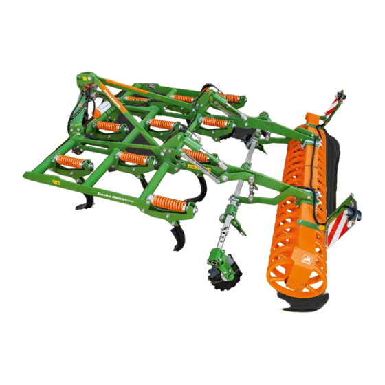
- Page 1 Original operating manual Mounted cultivator Cenio 3000 Cenio 3500 Cenio 4000 SmartLearning www.amazone.de...
- Page 2 Please enter the identification data of the implement. The identification data can be found on the rating plate.
-
Page 3: Table Of Contents
Preparing the implement for Warning symbols operation 4.5.1 Positions of the warning symbols 6.3.1 Adjusting the working depth of the coulters 4.5.2 Layout of the warning symbols 4.5.3 Description of the warning symbols MG6806-EN-GB | Q.1 | 26.07.2022 | © AMAZONE... - Page 4 10 Repairing the implement 10.1 Maintaining the implement 10.1.1 Maintenance schedule 10.1.2 Replacing tines with compression spring overload safety 10.1.3 Replacing tines with shear bolt overload safety 10.1.4 Replacing C-Mix-3 coulters MG6806-EN-GB | Q.1 | 26.07.2022 | © AMAZONE...
-
Page 5: About This Operating Manual
CAUTION Indicates a threat with low risk for light or moderately severe physical injuries. 1.1.2 Further instructions CMS-T-00002416-A.1 IMPORTANT Indicates a risk for damage to the implement. MG6806-EN-GB | Q.1 | 26.07.2022 | © AMAZONE... -
Page 6: Instructions
CMS-T-005678-B.1 Reactions to instructions are marked with an arrow. Example: 1. Instruction 1 Reaction to instruction 1 2. Instruction 2 1.1.3.2 Alternative instructions CMS-T-00000110-B.1 Alternative instructions are introduced with the word "or". MG6806-EN-GB | Q.1 | 26.07.2022 | © AMAZONE... -
Page 7: Lists
Lists without an essential order are shown as a list with bullets. Example: Point 1 Point 2 1.1.5 Item numbers in figures CMS-T-000023-B.1 A framed number in the text, e.g. a 1 , indicates an item number in an adjacent figure. MG6806-EN-GB | Q.1 | 26.07.2022 | © AMAZONE... -
Page 8: Other Applicable Documents
Your suggestions for improvement help us Technische Redaktion to create ever more user-friendly operating manuals. Postfach 51 Please send us your suggestions by post, fax or D-49202 Hasbergen email. Fax: +49 (0) 5405 501-234 E-Mail: td@amazone.de MG6806-EN-GB | Q.1 | 26.07.2022 | © AMAZONE... -
Page 9: Safety And Responsibility
2.1.2.1.1 Requirements for all persons working with the machine CMS-T-00002310-A.1 If the machine is used improperly, people can be injured or killed. To prevent accidents due to improper use, every person who works with MG6806-EN-GB | Q.1 | 26.07.2022 | © AMAZONE... - Page 10 Farmers are basically familiar with working with agricultural implements and can instruct agricultural helpers in how to use the implements if necessary. They can perform odd tasks and simple maintenance and repair work on agricultural implements themselves. MG6806-EN-GB | Q.1 | 26.07.2022 | © AMAZONE...
- Page 11 Passengers can fall, be run over and severely injured or killed due to machine movements. Ejected objects can hit and injure passengers. Do not let anybody ride on the machine. Do not let anybody climb onto the driving machine. MG6806-EN-GB | Q.1 | 26.07.2022 | © AMAZONE...
- Page 12 Non-observance of the technical limits values of the machine can result in accidents and serious personal injury or even death. Moreover, the machine can be damaged. The technical limit values can be found in the Technical Data. Comply with the technical limit values. MG6806-EN-GB | Q.1 | 26.07.2022 | © AMAZONE...
- Page 13 Missing warning symbols increase the risk of serious and lethal personal injury. Clean dirty warning symbols. Immediately replace any damaged and illegible warning symbols. Put the intended warning symbols on spare parts. MG6806-EN-GB | Q.1 | 26.07.2022 | © AMAZONE...
-
Page 14: Knowing And Preventing Dangers
Never look for leaks with your bare hands. Keep your body and face away from leaks. If liquids penetrate the body, consult a doctor immediately. MG6806-EN-GB | Q.1 | 26.07.2022 | © AMAZONE... -
Page 15: Safe Operation And Handling Of The Machine
Use only suitable tractors for coupling and transporting the implement. When the implement is coupled onto the tractor, make sure that the tractor's connecting device meets the implement requirements. Couple the implement properly to the tractor. MG6806-EN-GB | Q.1 | 26.07.2022 | © AMAZONE... - Page 16 If the machine is not properly prepared for road travel, it can result in serious traffic accidents. Check the lighting and identification for road travel for proper function. Remove coarse dirt from the implement. Follow the instructions in the section "Preparing the implement for road travel". MG6806-EN-GB | Q.1 | 26.07.2022 | © AMAZONE...
-
Page 17: Safe Maintenance And Modification
To ensure that the operating permit remains valid in accordance with national and international regulations, ensure that the specialist workshop only uses conversion parts, spare parts and special equipment approved by AMAZONE. MG6806-EN-GB | Q.1 | 26.07.2022 | © AMAZONE... - Page 18 Remove the ignition key and carry it with you. Remove the key from the battery circuit breaker. Wait until all parts that are still running come to a stop and that hot parts cool down. MG6806-EN-GB | Q.1 | 26.07.2022 | © AMAZONE...
- Page 19 Never linger under raised implement parts. If you have to work on or under raised machine parts, lower the implement parts or secure the raised implement parts with a mechanical support or hydraulic locking device. MG6806-EN-GB | Q.1 | 26.07.2022 | © AMAZONE...
- Page 20 CMS-T-00002325-B.1 Special equipment, accessories, and spare parts Special equipment, accessories, and spare parts that do not meet AMAZONE requirements can impede the operational safety of the implement and cause accidents. Only use original parts or parts that meet AMAZONE requirements.
-
Page 21: Safety Routines
If you are not sure if the protective equipment is properly installed and functional, have the protective equipment checked by a qualified specialist workshop. Make sure that the protective devices are properly installed and functional before any work on the implement. Replace damaged protective equipment. MG6806-EN-GB | Q.1 | 26.07.2022 | © AMAZONE... - Page 22 When climbing up and down, never hold onto the control elements. Accidental actuation of control elements can unintentionally activate potentially dangerous functions. When climbing down, never jump off of the machine. MG6806-EN-GB | Q.1 | 26.07.2022 | © AMAZONE...
-
Page 23: Intended Use
AMAZONE. Uses other than those specified under the intended use are considered as improper. The manufacturer is not liable for any damage resulting from improper use, solely the operator is responsible. MG6806-EN-GB | Q.1 | 26.07.2022 | © AMAZONE... -
Page 24: Product Description
Hose cabinet Working depth indicator on the tines Hydraulic working depth adjustment on the tines Automatic working depth adjustment of the Levelling with concave discs levelling Compression spring overload safety Spirit level MG6806-EN-GB | Q.1 | 26.07.2022 | © AMAZONE... -
Page 25: Overview Of The Implement With Shear Bolt Overload Safety
Special equipment is equipment that is not fitted on the implement or is only available in certain markets. The sales documents provide information on the equipment of your implement, or consult your dealer for more detailed information. MG6806-EN-GB | Q.1 | 26.07.2022 | © AMAZONE... -
Page 26: Protective Equipment
Hydraulic adjustment of the side discs 4.4 Protective equipment CMS-T-00000611-D.1 4.4.1 Road safety bars CMS-T-00000612-D.1 To protect from injuries during road transport, the road safety bar covers the tines on the rear harrow. CMS-I-00000088 MG6806-EN-GB | Q.1 | 26.07.2022 | © AMAZONE... -
Page 27: Warning Symbols
A warning symbol consists of two fields: Field 1 shows the following: A pictogram depicting the danger area, CMS-I-00000416 surrounded by triangular safety symbol The order number Field 2 shows a pictogram depicting how to avoid the danger. MG6806-EN-GB | Q.1 | 26.07.2022 | © AMAZONE... -
Page 28: Description Of The Warning Symbols
Do not let anybody climb onto the driving implement. CMS-I-000081 MD089 Risk of crushing from the machine parts unintentionally lowering Make sure that there is nobody standing in the danger area. CMS-I-00003027 MG6806-EN-GB | Q.1 | 26.07.2022 | © AMAZONE... - Page 29 Before you actuate the tractor hydraulic system, instruct persons away from the area between the tractor and the implement. Actuate the tractor hydraulic system only from the designated work station. CMS-I-000139 MG6806-EN-GB | Q.1 | 26.07.2022 | © AMAZONE...
- Page 30 CMS-I-00002253 MD 199 Risk of accident if the hydraulic system pressure is too high Only couple the implement to tractors with a maximum tractor hydraulic pressure of 210 bar. CMS-I-00000486 MG6806-EN-GB | Q.1 | 26.07.2022 | © AMAZONE...
-
Page 31: Rear Lighting And Identification
The lighting and identification for road travel can vary depending on the national regulations. 4.7 Rating plate on the implement CMS-T-00004505-F.1 Implement number Vehicle ID number Product Permissible technical implement weight Model year Year of manufacture CMS-I-00004294 MG6806-EN-GB | Q.1 | 26.07.2022 | © AMAZONE... -
Page 32: Soil Tillage Tools
The compression spring allows the tines to deflect in overload situations. CMS-I-00003022 4.8.1.2 Tines with shear bolt overload safety CMS-T-00004483-A.1 In the event of an overload, the shear bolt 1 shears off. CMS-I-00003021 MG6806-EN-GB | Q.1 | 26.07.2022 | © AMAZONE... -
Page 33: Coulters
C-Mix-3 coulter tip 100 mm C-Mix-3 Clip coulter tip 100 mm C-Mix-3 duck foot coulter tip C-Mix-3 HD duck foot coulter tip C-Mix-3 Clip duck foot coulter tip 4.8.2.2 C-Mix-3 coulters CMS-T-00004529-B.1 MG6806-EN-GB | Q.1 | 26.07.2022 | © AMAZONE... - Page 34 350 mm width Working 12-30 cm 10-20 cm 20-30 cm 3-10 cm depth Can be combined with C-Mix deflector plate 80 mm Can be combined with C- Mix-3 deflector plate 100 mm MG6806-EN-GB | Q.1 | 26.07.2022 | © AMAZONE...
- Page 35 Can be combined with C-Mix-3 deflector plate 100 mm 4.8.2.4 C-Mix-3 Clip coulters CMS-T-00004530-B.1 C-Mix-3 deflector plate C-Mix-3 Clip mount C-Mix-3 Clip coulter tip Retaining plate Coulter locking mechanism C-Mix-3 Clip assembly iron CMS-I-00003311 MG6806-EN-GB | Q.1 | 26.07.2022 | © AMAZONE...
- Page 36 Can be combined with C-Mix-3 deflector plate 100 mm 4.8.2.5 Deflector guide arrangement CMS-T-00004199-A.1 4.8.2.5.1 Deflector guide arrangement on the Cenio 3000 CMS-T-00004200-A.1 The deflector guide arrangement is variable. The figure shows the recommended, factory-mounted deflector guide arrangement. The arrows show the throw direction produced by the deflector guides.
- Page 37 4.8.2.5.2 Deflector guide arrangement on the Cenio 3500 CMS-T-00004201-A.1 The deflector guide arrangement is variable. The figure shows the recommended, factory-mounted deflector guide arrangement. The arrows show the throw direction produced by the deflector guides. MG6806-EN-GB | Q.1 | 26.07.2022 | © AMAZONE...
- Page 38 4.8.2.5.3 Deflector guide arrangement on the Cenio 4000 CMS-T-00004202-A.1 The deflector guide arrangement is variable. The figure shows the recommended, factory-mounted deflector guide arrangement. The arrows show the throw direction produced by the deflector guides. MG6806-EN-GB | Q.1 | 26.07.2022 | © AMAZONE...
- Page 39 4 | Product description Soil tillage tools CMS-I-00003018 MG6806-EN-GB | Q.1 | 26.07.2022 | © AMAZONE...
-
Page 40: Greendrill Pack Top Seed Drill
The GreenDrill is mounted on the implement. The GreenDrill seeds fine seeds and catch crops during soil tillage. CMS-I-00000050 4.10 Threaded cartridge CMS-T-00001776-E.1 The threaded cartridge contains the following items: Documents Aids CMS-I-00002306 MG6806-EN-GB | Q.1 | 26.07.2022 | © AMAZONE... -
Page 41: Technical Data
3-30 cm Tripping force of the compression spring 500 kg overload safety 5.3 Permitted mounting categories CMS-T-00004066-A.1 3-point mounting frame Category 3 and Category 3N 5.4 Optimal working speed CMS-T-00004068-B.1 8-15 km/h MG6806-EN-GB | Q.1 | 26.07.2022 | © AMAZONE... -
Page 42: Performance Characteristics Of The Tractor
The emission sound pressure level mainly depends on the vehicle used. 5.7 Drivable slope inclination CMS-T-00002297-E.1 Across the slope On left in direction of travel 15 % On right in direction of travel 15 % MG6806-EN-GB | Q.1 | 26.07.2022 | © AMAZONE... - Page 43 5 | Technical data Drivable slope inclination Up the slope and down the slope Up the slope 15 % Down the slope 15 % MG6806-EN-GB | Q.1 | 26.07.2022 | © AMAZONE...
-
Page 44: Preparing The Machine
Total weight of front-mounted implement or front ballast Permissible total weight of rear-mounted implement or rear ballast Distance between the centre of gravity of the front-mounted implement or the front ballast and the centre of the front axle MG6806-EN-GB | Q.1 | 26.07.2022 | © AMAZONE... - Page 45 T b 0,2 T b Vmin Vmin Vmin CMS-I-00000513 2. Calculate the actual front axle load. × × - × G a b T b G c + d Vtat Vtat Vtat CMS-I-00000516 MG6806-EN-GB | Q.1 | 26.07.2022 | © AMAZONE...
- Page 46 Tyre load according to according to capacity for two tractor operating calculation tractor tyres manual ≤ Minimum front ballasting ≤ Total weight ≤ ≤ Front axle load ≤ ≤ Rear axle load MG6806-EN-GB | Q.1 | 26.07.2022 | © AMAZONE...
-
Page 47: Coupling The Implement
6.2.2 Attaching the backstop profiles for the lower links CMS-T-00001398-A.1 1. Put the backstop profiles 1 on the lower link pins 2 . 2. Secure the backstop profiles with the linch pin CMS-I-00001219 MG6806-EN-GB | Q.1 | 26.07.2022 | © AMAZONE... -
Page 48: Attaching The Ball Sleeve For The Top Link
Stickers are applied on the implement for the markings, which illustrate the respective hydraulic functions. The tractor control unit is used with different types of actuation, depending on the hydraulic function: CMS-I-00000121 MG6806-EN-GB | Q.1 | 26.07.2022 | © AMAZONE... - Page 49 Install the supplied coupling sleeve on the pressureless hydraulic oil return. 1. Depressurise the hydraulic system between the tractor and the implement using the tractor control unit. 2. Clean the hydraulic plugs. MG6806-EN-GB | Q.1 | 26.07.2022 | © AMAZONE...
-
Page 50: Coupling The Power Supply
4 are correctly locked. CMS-I-00001225 6.2.8 Aligning the implement horizontally CMS-T-00004540-B.1 A spirit level is attached to the implement frame. The spirit level shows the alignment of the implement in the direction of travel. MG6806-EN-GB | Q.1 | 26.07.2022 | © AMAZONE... -
Page 51: Preparing The Implement For Operation
For the coulters to be able to reach the set working depth, drive forwards. 8. Insert pins 2 into the group of holes B on both sides. 9. Secure the pin with a linch pin. MG6806-EN-GB | Q.1 | 26.07.2022 | © AMAZONE... -
Page 52: Adjusting The Working Depth Of The Levelling
3 out of the group of holes. To change the working depth, swivel the setting lever up or down. CMS-I-00003060 6. Insert the pin 3 in the group of holes. MG6806-EN-GB | Q.1 | 26.07.2022 | © AMAZONE... - Page 53 2. Remove the lock nut 2 . 3. Adjust the length of the threaded spindle on the hexagon 1 with a spanner. 4. Tighten the lock nut. 5. Adjust the second spindle to the same length. CMS-I-00003061 MG6806-EN-GB | Q.1 | 26.07.2022 | © AMAZONE...
-
Page 54: Preparing The Spring Steel Closer For Operation
3. Turn the edge levelling disc to the desired position. 4. Tighten the bolts 1 . 5. Loosen the bolts 2 . CMS-I-00003276 6. Move the edge levelling disc disc up or down. 7. Tighten the bolts 2 . MG6806-EN-GB | Q.1 | 26.07.2022 | © AMAZONE... -
Page 55: Adjusting The Scraper To The Roller
Permitted distances A between the roller element and scraper: Wedge ring roller: 12 mm ± 2 mm Wedge ring roller with matrix tyre profile: 13 mm ± 2 mm Tooth packer roller: at least 1 mm CMS-I-00002071 MG6806-EN-GB | Q.1 | 26.07.2022 | © AMAZONE... -
Page 56: Removing The Road Safety Bars
2 . 3. Secure the road safety bars with tensioners 3 . CMS-I-00000518 6.3.7 Adjusting the trailing elements CMS-T-00002429-G.1 1. Take the setting lever 1 from the holder. CMS-I-00002241 MG6806-EN-GB | Q.1 | 26.07.2022 | © AMAZONE... - Page 57 CMS-I-00002243 7. Put the setting lever 1 in the holder. 8. Secure the setting lever with a linch pin 2 . CMS-I-00002242 MG6806-EN-GB | Q.1 | 26.07.2022 | © AMAZONE...
-
Page 58: Preparing The Machine For Road Travel
CMS-I-00000517 6.4.3 Reducing the implement width to the permitted transport width CMS-T-00005110-B.1 The Cenio 3000 and Cenio 3500 with duck foot coulters or wing coulters exceed the permitted width. Remove the outer coulters. MG6806-EN-GB | Q.1 | 26.07.2022 | © AMAZONE... -
Page 59: Calculating The Permissible Payload
Maximum payload = Permissible technical implement weight - tare weight 1. Read the permissible technical implement weight from the rating plate. To determine the tare weight, weigh the implement with empty hoppers. 3. Calculate the payload. MG6806-EN-GB | Q.1 | 26.07.2022 | © AMAZONE... -
Page 60: Using The Machine
To prevent lateral loads when driving in curves on the headlands, raise the soil tillage tools. When the direction of the implement matches that of the direction of travel, lower the soil tillage tools. MG6806-EN-GB | Q.1 | 26.07.2022 | © AMAZONE... -
Page 61: Eliminating Faults
The tine and coulter have hit a solid see page 58 overload safety sheared off obstacle. The working depth is uneven The hydraulic cylinders have see page 58 across the entire implement width different lengths MG6806-EN-GB | Q.1 | 26.07.2022 | © AMAZONE... - Page 62 Different working depths across the working width CMS-T-00005120-A.1 1. completely extend the hydraulic cylinders with the "green" tractor control unit. 2. Hold the "green" tractor control unit for 10 seconds. The hydraulic cylinders will be synchronised. MG6806-EN-GB | Q.1 | 26.07.2022 | © AMAZONE...
-
Page 63: Parking The Machine
4. Relieve the tractor's lower link 2 . 5. Uncouple the tractor lower links 2 from the CMS-I-00001249 implement from the tractor seat. 6. Drive the tractor forward. MG6806-EN-GB | Q.1 | 26.07.2022 | © AMAZONE... -
Page 64: Driving The Tractor Away From The Implement
CMS-I-00004044 9.3 Uncoupling the power supply CMS-T-00001402-F.1 1. Pull out the plug 1 for the power supply. CMS-I-00001048 2. Hang the plugs 1 in the hose cabinet. CMS-I-00001248 MG6806-EN-GB | Q.1 | 26.07.2022 | © AMAZONE... -
Page 65: Disconnecting The Hydraulic Hose Lines
3. Disconnect the hydraulic hose lines 1 . 4. Put the dust caps on the hydraulic sockets. CMS-I-00001065 5. Hang the hydraulic hose lines 1 in the hose cabinet. CMS-I-00001250 MG6806-EN-GB | Q.1 | 26.07.2022 | © AMAZONE... -
Page 66: Repairing The Implement
Checking the top link pin and lower link pin see page 67 Every 50 operating hours / weekly Checking the hydraulic hose lines see page 67 Every 200 operating hours / Every 3 months Checking the rollers see page 67 MG6806-EN-GB | Q.1 | 26.07.2022 | © AMAZONE... -
Page 67: Replacing Tines With Compression Spring Overload Safety
Install the bolts on the tine. 410 Nm CMS-I-00003072 10.1.3 Replacing tines with shear bolt overload safety CMS-T-00004183-B.1 INTERVAL as required WARNING Risk of crushing due to lowering of the implement Raise the implement only slightly. MG6806-EN-GB | Q.1 | 26.07.2022 | © AMAZONE... -
Page 68: Replacing C-Mix-3 Coulters
Do not allow carriage bolts to rotate. 1. Remove the bolts. 2. Replace the coulters. 3. Install the bolts. 4. Tighten the bolts. 145 Nm 5. Retighten the bolts after 5 operating hours. CMS-I-00003077 MG6806-EN-GB | Q.1 | 26.07.2022 | © AMAZONE... -
Page 69: Replacing The C-Mix-3 Clip Coulter
10.1.6 Replacing the discs CMS-T-00002327-E.1 INTERVAL as required Original disc diameter Wear limit 46 cm 36 cm 48 cm 40 cm 61 cm 43 cm 66 cm 46 cm MG6806-EN-GB | Q.1 | 26.07.2022 | © AMAZONE... -
Page 70: Checking The Levelling Connection
3. Remove the washer 2 . 4. Fasten the new disc with the 4 bolts. CMS-I-00002450 10.1.7 Checking the levelling connection CMS-T-00004190-B.1 INTERVAL After initial operation Check the bolts for tightness. 210 Nm CMS-I-00003080 MG6806-EN-GB | Q.1 | 26.07.2022 | © AMAZONE... -
Page 71: Checking The Rollers
After initial operation Every 50 operating hours weekly 1. Check the hydraulic hose lines for damage, such as chafing point, cuts, tears and deformation. 2. Check the hydraulic hose lines for leaks. MG6806-EN-GB | Q.1 | 26.07.2022 | © AMAZONE... - Page 72 Hydraulic hose lines must not be more than 6 years old. 3. Check the manufacturing date 1 . CMS-I-00000532 4. Have any worn, damaged or aged hydraulic hose lines immediately replaced at a specialist workshop. 5. Retighten loose bolted connections. MG6806-EN-GB | Q.1 | 26.07.2022 | © AMAZONE...
-
Page 73: Lubricating The Implement
Only grease the implement with the lubricants listed in the technical data. CMS-I-00002270 Press the dirty grease completely out of the bearings. MG6806-EN-GB | Q.1 | 26.07.2022 | © AMAZONE... -
Page 74: Overview Of Lubrication Points
10 | Repairing the implement Lubricating the implement 10.2.1 Overview of lubrication points CMS-T-00004553-C.1 CMS-I-00003280 Every 20 operating hours CMS-I-00003279 MG6806-EN-GB | Q.1 | 26.07.2022 | © AMAZONE... -
Page 75: Cleaning The Implement
Always maintain a minimum distance of 300 mm between the high-pressure nozzle and the machine. Do not exceed a water pressure of 120 bar. Clean the machine with a high-pressure cleaner or a hot water high-pressure cleaner. MG6806-EN-GB | Q.1 | 26.07.2022 | © AMAZONE... -
Page 76: Loading The Implement
Required load-bearing capacity per sling 1000 kg 1. Attach the slings for lifting on the intended lashing points. 2. Slowly lift the implement. MG6806-EN-GB | Q.1 | 26.07.2022 | © AMAZONE... -
Page 77: Appendix
CMS-T-00000372-C.1 12.1 Bolt tightening torques CMS-T-00000373-C.1 CMS-I-000260 NOTE Unless specified otherwise, the bolt tightening torques listed in the table apply. 10.9 12.9 M8x1 16(17) M10x1 18(19) M12x1.5 M 14x1.5 M16x1.5 M18x1.5 M20x1.5 MG6806-EN-GB | Q.1 | 26.07.2022 | © AMAZONE... -
Page 78: Other Applicable Documents
1050 1500 1800 M27x2 1150 1600 1950 1450 2000 2400 M30x2 1600 2250 2700 CMS-I-00000065 20.4 40.7 70.5 12.2 Other applicable documents CMS-T-00000615-A.1 Tractor operating manual Operating manual for the GreenDrill 200-E MG6806-EN-GB | Q.1 | 26.07.2022 | © AMAZONE... -
Page 79: Directories
Tractor In this operating manual, the designation tractor is always used, even for other agricultural tractor units. Implements are mounted on the tractor or towed by the tractor. MG6806-EN-GB | Q.1 | 26.07.2022 | © AMAZONE... -
Page 80: Index
Preparing for road travel Replacing C-Mix-3 coulters Preparing the spring steel closer for operation 50 Replacing the C-Mix-3 Clip coulter Lighting and identification Rear loading Dimensions Loads Discs calculation replacing Lower link pin Documents checking MG6806-EN-GB | Q.1 | 26.07.2022 | © AMAZONE... - Page 81 Total weight removing calculation Road travel Tractor Preparing the machine Calculating the required tractor characteristics 40 Roller Trailing elements Adjusting the scraper adjustment checking Transport width reducing Scraper Tyre load capacity adjusting calculation MG6806-EN-GB | Q.1 | 26.07.2022 | © AMAZONE...
- Page 82 Adjusting the edge levelling discs Adjusting the harrow system Adjusting the spring blade system Adjusting the spring clearer system Adjusting the trailing elements Hydraulic coulter adjustment Manual coulter adjustment Manual levelling unit adjustment Working speed MG6806-EN-GB | Q.1 | 26.07.2022 | © AMAZONE...
- Page 84 AMAZONEN-WERKE H. DREYER SE & Co. KG Postfach 51 49202 Hasbergen-Gaste Germany +49 (0) 5405 501-0 amazone@amazone.de www.amazone.de MG6806-EN-GB | Q.1 | 26.07.2022 | © AMAZONE...
Need help?
Do you have a question about the Cenio 3000 and is the answer not in the manual?
Questions and answers