Sign In
Upload
Download
Table of Contents
Contents
Add to my manuals
Delete from my manuals
Share
URL of this page:
HTML Link:
Bookmark this page
Add
Manual will be automatically added to "My Manuals"
Print this page
×
Bookmark added
×
Added to my manuals
Manuals
Brands
Amazone Manuals
Tiller
Ceus 4000-2TX
Operating manual
Amazone Ceus 4000-2TX Operating Manual
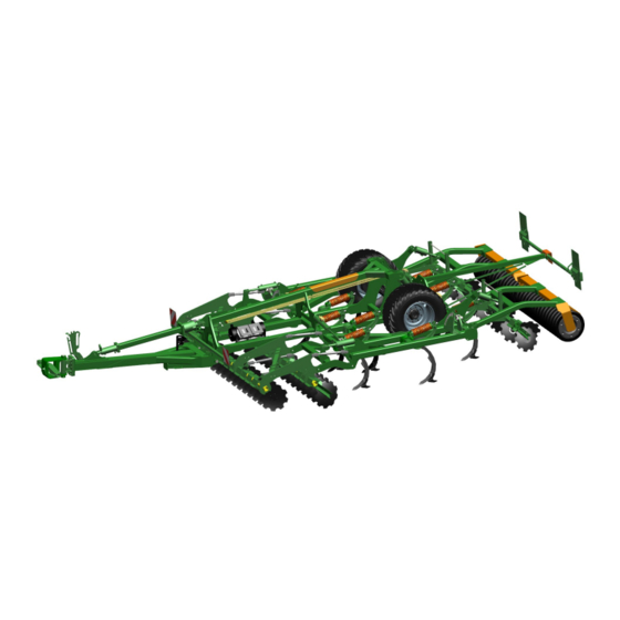
Trailed cultivator disc harrow combination
Hide thumbs
1
2
3
4
Table Of Contents
5
6
7
8
9
10
11
12
13
14
15
16
17
18
19
20
21
22
23
24
25
26
27
28
29
30
31
32
33
34
35
36
37
38
39
40
41
42
43
44
45
46
47
48
49
50
51
52
53
54
55
56
57
58
59
60
61
62
63
64
65
66
67
68
69
70
71
72
73
74
75
76
77
78
79
80
81
82
83
84
85
86
87
88
89
90
91
92
93
94
95
96
97
98
99
100
101
102
103
104
105
106
107
108
109
110
111
112
113
114
115
116
117
118
119
120
121
122
123
124
125
126
127
128
129
130
131
132
page
of
132
Go
/
132
Contents
Table of Contents
Bookmarks
Table of Contents
Table of Contents
1 User Information
Purpose of the Document
Locations in the Operating Manual
Diagrams Used
2 General Safety Instructions
Obligations and Liability
Representation of Safety Symbols
Organisational Measures
Safety and Protection Equipment
Informal Safety Measures
User Training
Safety Measures in Normal Operation
Dangers from Residual Energy
Maintenance and Repair Work, Fault Elimination
Constructive Changes
Spare and Wear Parts and Aids
Cleaning and Disposal
User Workstation
Warning Pictograms and Other Signs on the Machine
Positioning of Warning Pictograms and Other Labels
Dangers of Not Observing Safety Instructions
Safety-Conscious Working
Safety Information for Users
General Safety and Accident Prevention Information
Hydraulic System
Electrical System
Brake System
Tyres
Coupled Machines
Cleaning, Maintenance and Repairs
3 Loading and Unloading
4 Product Description
Overview of Subassemblies
Safety and Protection Equipment
Transportation Equipment
Intended Use
Danger Area and Danger Points
Rating Plate and CE Marking
Technical Data
Weights Basic Machine and Modules
Lubricants
Necessary Tractor Equipment
Noise Production Data
5 Structure and Function
Dual-Circuit Service Brake System
Coupling the Brake and Supply Lines
Uncoupling the Brake and Supply Lines
Parking Brake
Disc Array
Tine Array with Coulters
Tines
Coulter
Coulter C-MIX
Levelling Unit
Boundary Discs / Side Closer
Rollers
Rear Harrow (Optional)
Hydraulic Connections
Coupling Hydraulic Hose Lines
Disconnecting Hydraulic Hose Lines
Running Gear
Drawbar
Hydraulic Drawbar Control
Jack
Guide Wheels
Safety Chain for Implements Without Brake System
Immobiliser for Towing Device
Hectare Counter (Optional)
Transport Box
6 Commissioning
Checking the Suitability of the Tractor
Calculating the Actual Values for the Total Tractor Weight, Tractor Axle Loads and Load Capacities, as Well as the Minimum Ballast
Requirements for Tractor Operation with Attached Machines
Machines Without Their Own Brake System
Securing the Tractor/Machine against Unintentional Start-Up and Rolling
7 Coupling and Uncoupling the Machine
Coupling the Implement
Uncoupling the Implement
8 Adjustments
Performing Mechanical Adjustments Using an Adjustment Spindle
Adjusting the Working Depth of the Disc Array
Aligning the Disc Gangs with each Other
Adjusting the Throughput of the Disc Gangs
Adjusting the Working Depth of the Coulters
Aligning the Implement Horizontally in Working Position
Setting the Working Depth of the Levelling Unit
Adjusting the Stripper of the Wedge Ring Rollers
Mounting / Dismounting the Roller
Height of the Ball Bracket / Towing Eye
9 Transportation
10 Use of the Machine
Working Position and Operating Position of the Implement
Converting from Working to Transport Position
Converting from Transport to Working Position
Moving the Drawbar Cylinder into Transport and Working Position
Moving the Side Discs into Transport Position / Working Position
Moving the Side Elements of the Levelling Unit into Transport Position / Working Position
Moving the Rear Harrow into Transport Position / Working Position
Operation
Headland
11 Faults
12 Cleaning, Maintenance and Repairs
Cleaning
Lubrication Instructions
Maintenance Plan - Overview
Coulter Replacement and Tine Replacement
Tine Replacement
Coulter Replacement
Changing the C-MIX Clip Coulter
Installing and Removing the Disc Segments (Workshop Work)
Replacing Discs (Workshop Work)
Tine Connection
Checking the Roller
Disc Carrier Connection
Axle (Running Gear / Support Wheel) and Brake
12.10.1 Hydraulic Brakes
12.10.2 Parking Brake
Check the Coupling Device
Tyres / Wheels
12.12.1 Tyre Pressures
12.12.2 Fitting Tyres
Hydraulic Cylinder for Folding
Hydraulic System (Workshop Work)
12.14.1 Labelling Hydraulic Hose Lines
12.14.2 Maintenance Intervals
12.14.3 Inspection Criteria for Hydraulic Hose Lines
12.14.4 Installation and Removal of Hydraulic Hose Lines
Lower Link Pins
13 Hydraulic Circuit Diagram
Screw Tightening Torques
14 Checklist for Using the Implement
Advertisement
Quick Links
1
Disc Array
Download this manual
Trailed cultivator disc harrow combination
MG6159
BAG0183.2 01.19
Printed in Germany
en
Operating Manual
az
Ceus 4000-2TX
Ceus 5000-2TX
Ceus 6000-2TX
Ceus 7000-2TX
Read and observe this
operating manual before using
the implement for the first time!
Keep it in a safe place for
future use!
Table of
Contents
Previous
Page
Next
Page
1
2
3
4
5
Advertisement
Table of Contents
Need help?
Do you have a question about the Ceus 4000-2TX and is the answer not in the manual?
Ask a question
Questions and answers
Related Manuals for Amazone Ceus 4000-2TX
Tiller Amazone Catros 3001 Operating Manual
Compact disc cultivator (88 pages)
Tiller Amazone Centaur 4001-2 Series Operating Manual
Mulch cultivator (106 pages)
Tiller Amazone Catros 3002-T Operating Manual
Compact disc cultivator (76 pages)
Tiller Amazone Catros 4001-2TS Operating Manual
Compact disc cultivator (90 pages)
Tiller Amazone Cenius 4003-2T Special Operating Manual
Mulch cultivator (96 pages)
Tiller Amazone CatrosXL 4003-2 Operating Instructions Manual
Mounted compact disc cultivator (82 pages)
Tiller Amazone Catros 4002-2TS Operating Manual
Trailed compact disc cultivator with swivelling running gear (116 pages)
Tiller Amazone Cenius 4003-2TX Operating Manual
Trailed cultivator (126 pages)
Tiller Amazone Cenius 4002-2 Super Operating Manual
Mulch cultivator (84 pages)
Tiller Amazone Ceus 6000-2TX Operating Manual
Trailed cultivator disc harrow combination (132 pages)
Tiller Amazone Ceus 7000-2TX Operating Manual
Trailed cultivator disc harrow combination (132 pages)
Tiller Amazone Cobra 6000-2TX Original Operating Manual
Trailed shallow cultivator (122 pages)
Tiller Amazone Cobra 6000-2TX Original Operating Manual
Trailed shallow cultivator (138 pages)
Tiller Amazone Cenio 4000-2 Original Operating Manual
Mounted cultivator (92 pages)
Tiller Amazone Cenius 8003-2TX Operating Manual
Trailed cultivator (126 pages)
Tiller Amazone Cenio 4000 Original Operating Manual
Mounted cultivator (84 pages)
This manual is also suitable for:
Ceus 6000-2tx
Ceus 7000-2tx
Ceus 5000-2tx
Table of Contents
Print
Rename the bookmark
Delete bookmark?
Delete from my manuals?
Login
Sign In
OR
Sign in with Facebook
Sign in with Google
Upload manual
Upload from disk
Upload from URL


Need help?
Do you have a question about the Ceus 4000-2TX and is the answer not in the manual?
Questions and answers