
Related Manuals for Amazone Cobra 6000-2TX


Summary of Contents for Amazone Cobra 6000-2TX
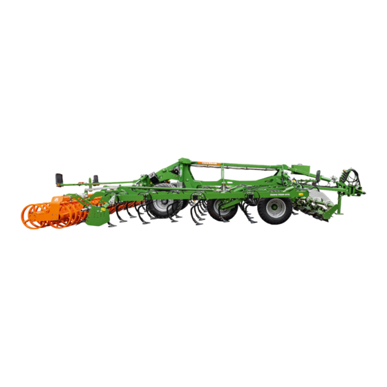
- Page 1 Original operating manual Trailed shallow cultivator Cobra 6000-2TX Cobra 7000-2TX SmartLearning www.amazone.de...
- Page 2 Please enter the identification data of the implement. The identification data can be found on the rating plate.
-
Page 3: Table Of Contents
Brake valve for pneumatic brake system 6.1.2 Determining the required coupling devices 4.4.5 Wheel chocks 6.1.3 Comparing the permissible DC 4.4.6 Safety chain value with actual DC value Warning symbols Coupling the implement MG7478-EN-GB | C.1 | 19.08.2022 | © AMAZONE... - Page 4 10 Repairing the implement crushboard working depth 10.1 Maintaining the implement Using the levelling unit 10.1.1 Maintenance schedule 7.5.1 Activating the levelling unit and 10.1.2 Checking the connection of the adjusting the tilt cutting roller MG7478-EN-GB | C.1 | 19.08.2022 | © AMAZONE...
- Page 5 11 Transporting the machine 11.1 Lashing the implement 11.2 Manoeuvring the implement with pneumatic brake system 12 Appendix 12.1 Bolt tightening torques 12.2 Other applicable documents 13 Directories 13.1 Glossary 13.2 Index MG7478-EN-GB | C.1 | 19.08.2022 | © AMAZONE...
-
Page 7: About This Operating Manual
CAUTION Indicates a threat with low risk for light or moderately severe physical injuries. 1.1.2 Further instructions CMS-T-00002416-A.1 IMPORTANT Indicates a risk for damage to the implement. MG7478-EN-GB | C.1 | 19.08.2022 | © AMAZONE... -
Page 8: Instructions
CMS-T-005678-B.1 Reactions to instructions are marked with an arrow. Example: 1. Instruction 1 Reaction to instruction 1 2. Instruction 2 1.1.3.2 Alternative instructions CMS-T-00000110-B.1 Alternative instructions are introduced with the word "or". MG7478-EN-GB | C.1 | 19.08.2022 | © AMAZONE... -
Page 9: Lists
Lists without an essential order are shown as a list with bullets. Example: Point 1 Point 2 1.1.5 Item numbers in figures CMS-T-000023-B.1 A framed number in the text, e.g. a 1 , indicates an item number in an adjacent figure. MG7478-EN-GB | C.1 | 19.08.2022 | © AMAZONE... -
Page 10: Other Applicable Documents
Your suggestions for improvement help us Technische Redaktion to create ever more user-friendly operating manuals. Postfach 51 Please send us your suggestions by post, fax or D-49202 Hasbergen email. Fax: +49 (0) 5405 501-234 E-Mail: td@amazone.de MG7478-EN-GB | C.1 | 19.08.2022 | © AMAZONE... -
Page 11: Safety And Responsibility
2.1.2.1.1 Requirements for all persons working with the machine CMS-T-00002310-A.1 If the machine is used improperly, people can be injured or killed. To prevent accidents due to improper use, every person who works with MG7478-EN-GB | C.1 | 19.08.2022 | © AMAZONE... - Page 12 Farmers are basically familiar with working with agricultural implements and can instruct agricultural helpers in how to use the implements if necessary. They can perform odd tasks and simple maintenance and repair work on agricultural implements themselves. MG7478-EN-GB | C.1 | 19.08.2022 | © AMAZONE...
- Page 13 Passengers can fall, be run over and severely injured or killed due to machine movements. Ejected objects can hit and injure passengers. Do not let anybody ride on the machine. Do not let anybody climb onto the driving machine. MG7478-EN-GB | C.1 | 19.08.2022 | © AMAZONE...
- Page 14 Non-observance of the technical limits values of the machine can result in accidents and serious personal injury or even death. Moreover, the machine can be damaged. The technical limit values can be found in the Technical Data. Comply with the technical limit values. MG7478-EN-GB | C.1 | 19.08.2022 | © AMAZONE...
- Page 15 Missing warning symbols increase the risk of serious and lethal personal injury. Clean dirty warning symbols. Immediately replace any damaged and illegible warning symbols. Put the intended warning symbols on spare parts. MG7478-EN-GB | C.1 | 19.08.2022 | © AMAZONE...
-
Page 16: Knowing And Preventing Dangers
Never look for leaks with your bare hands. Keep your body and face away from leaks. If liquids penetrate the body, consult a doctor immediately. MG7478-EN-GB | C.1 | 19.08.2022 | © AMAZONE... -
Page 17: Safe Operation And Handling Of The Machine
Use only suitable tractors for coupling and transporting the implement. When the implement is coupled onto the tractor, make sure that the tractor's connecting device meets the implement requirements. Couple the implement properly to the tractor. MG7478-EN-GB | C.1 | 19.08.2022 | © AMAZONE... - Page 18 If the machine is not properly prepared for road travel, it can result in serious traffic accidents. Check the lighting and identification for road travel for proper function. Remove coarse dirt from the implement. Follow the instructions in the section "Preparing the implement for road travel". MG7478-EN-GB | C.1 | 19.08.2022 | © AMAZONE...
-
Page 19: Safe Maintenance And Modification
To ensure that the operating permit remains valid in accordance with national and international regulations, ensure that the specialist workshop only uses conversion parts, spare parts and special equipment approved by AMAZONE. MG7478-EN-GB | C.1 | 19.08.2022 | © AMAZONE... - Page 20 Remove the ignition key and carry it with you. Remove the key from the battery circuit breaker. Wait until all parts that are still running come to a stop and that hot parts cool down. MG7478-EN-GB | C.1 | 19.08.2022 | © AMAZONE...
- Page 21 Never linger under raised implement parts. If you have to work on or under raised machine parts, lower the implement parts or secure the raised implement parts with a mechanical support or hydraulic locking device. MG7478-EN-GB | C.1 | 19.08.2022 | © AMAZONE...
- Page 22 CMS-T-00002325-B.1 Special equipment, accessories, and spare parts Special equipment, accessories, and spare parts that do not meet AMAZONE requirements can impede the operational safety of the implement and cause accidents. Only use original parts or parts that meet AMAZONE requirements.
-
Page 23: Safety Routines
If you are not sure if the protective equipment is properly installed and functional, have the protective equipment checked by a qualified specialist workshop. Make sure that the protective devices are properly installed and functional before any work on the implement. Replace damaged protective equipment. MG7478-EN-GB | C.1 | 19.08.2022 | © AMAZONE... - Page 24 When climbing up and down, never hold onto the control elements. Accidental actuation of control elements can unintentionally activate potentially dangerous functions. When climbing down, never jump off of the machine. MG7478-EN-GB | C.1 | 19.08.2022 | © AMAZONE...
-
Page 25: Intended Use
AMAZONE. Uses other than those specified under the intended use are considered as improper. The manufacturer is not liable for any damage resulting from improper use, solely the operator is responsible. MG7478-EN-GB | C.1 | 19.08.2022 | © AMAZONE... -
Page 26: Product Description
12 Levelling 13 Rear harrow 14 Side closer 15 Drag tines 16 Tine with coulter 17 Tine row 18 Support wheel 19 Cutting roller 20 Mechanical working depth adjustment of the coulters MG7478-EN-GB | C.1 | 19.08.2022 | © AMAZONE... -
Page 27: Function Of The Implement
4.2 Function of the implement CMS-T-00009218-A.1 The leading tool breaks clods or chops organic crops residues. The tines loosen up the soil. The levelling unit levels the soil. The roller reconsolidates the soil. MG7478-EN-GB | C.1 | 19.08.2022 | © AMAZONE... -
Page 28: Special Equipment
Pneumatic brake system Safety chain Roller with or without rear harrow Double harrow Spring clearer system for U-profile roller UW 580 Preparation for working without the roller Service box Hectare counter Traction assistance MG7478-EN-GB | C.1 | 19.08.2022 | © AMAZONE... -
Page 29: Protective Equipment
4.4.2 Stop tap on the hydraulic drawbar CMS-T-00009235-A.1 The stop tap ensures that the hydraulic drawbar does not move during road travel. CMS-I-00006975 4.4.3 Parking brake CMS-T-00009984-A.1 The parking brake prevents the uncoupled implement from rolling away. MG7478-EN-GB | C.1 | 19.08.2022 | © AMAZONE... -
Page 30: Brake Valve For Pneumatic Brake System
The brake valve has a release valve 2 with a control knob 1 . CMS-I-00004845 4.4.5 Wheel chocks CMS-T-00004297-B.1 The wheel chocks prevent the uncoupled implement from rolling away. CMS-I-00003288 MG7478-EN-GB | C.1 | 19.08.2022 | © AMAZONE... -
Page 31: Safety Chain
CMS-I-00003562 4.5 Warning symbols CMS-T-00009221-A.1 4.5.1 Positions of the warning symbols CMS-T-00009223-A.1 MD094 MD174 MD095 MD102 MD199 MD096 MD078 MD078 MD108 MD108 MD082 MD155 MD089 MD079 CMS-I-00006418 MG7478-EN-GB | C.1 | 19.08.2022 | © AMAZONE... - Page 32 4 | Product description Warning symbols MD174 MD078 MD079 MD089 MD155 MD082 MD108 MD108 MD078 CMS-I-00006417 MD101 MD101 CMS-I-00006416 MG7478-EN-GB | C.1 | 19.08.2022 | © AMAZONE...
-
Page 33: Layout Of The Warning Symbols
A warning symbol consists of two fields: Field 1 shows the following: A pictogram depicting the danger area, CMS-I-00000416 surrounded by triangular safety symbol The order number Field 2 shows a pictogram depicting how to avoid the danger. MG7478-EN-GB | C.1 | 19.08.2022 | © AMAZONE... -
Page 34: Description Of The Warning Symbols
Do not let anybody climb onto the driving implement. CMS-I-000081 MD089 Risk of crushing from the machine parts unintentionally lowering Make sure that there is nobody standing in the danger area. CMS-I-00003027 MG7478-EN-GB | C.1 | 19.08.2022 | © AMAZONE... - Page 35 Never look for leaks in hydraulic hose lines using your hand or fingers. Never attempt to plug leaks in hydraulic hose lines using your hand or fingers. If you are injured by hydraulic oil, consult a doctor immediately. CMS-I-000216 MG7478-EN-GB | C.1 | 19.08.2022 | © AMAZONE...
- Page 36 MD 108 Severe injuries due to incorrect handling of the hydraulic accumulator when it is under pressure Have the pressurised hydraulic accumulator checked and repaired only by a qualified specialist workshop. CMS-I-00004027 MG7478-EN-GB | C.1 | 19.08.2022 | © AMAZONE...
- Page 37 To do so, use the parking brake and/or wheel chocks. CMS-I-00000458 MD 199 Risk of accident if the hydraulic system pressure is too high Only couple the implement to tractors with a maximum tractor hydraulic pressure of 210 bar. CMS-I-00000486 MG7478-EN-GB | C.1 | 19.08.2022 | © AMAZONE...
-
Page 38: Lighting And Identification For Road Travel
Rear lights, brake lights, and turn indicators Reflector, yellow CMS-I-00003575 NOTE The lighting and identification for road travel can vary depending on the national regulations. 4.6.2 Front lighting and identification CMS-T-00009971-A.1 Warning signs Reflector, white CMS-I-00004522 MG7478-EN-GB | C.1 | 19.08.2022 | © AMAZONE... -
Page 39: Rating Plates And The Ce Mark
Permissible technical trailer load for a drawbar trailer vehicle with pneumatic brake A0 Permissible technical drawbar load A1 Permissible technical axle load for axle 1 A2 Permissible technical axle load for axle 2 MG7478-EN-GB | C.1 | 19.08.2022 | © AMAZONE... -
Page 40: Other Information On The Implement
1 and open in position ME1677 CMS-I-00003535 4.9 Soil tillage tools CMS-T-00009236-A.1 4.9.1 ECO leaf spring tines CMS-T-00009249-A.1 The leaf springs protect the tines against overloads. CMS-I-00006352 MG7478-EN-GB | C.1 | 19.08.2022 | © AMAZONE... -
Page 41: Coulters
4.9.2.2 Work patterns of the coulters CMS-T-00009490-A.1 Coulter Work pattern Narrow coulter 50 mm HD narrow coulter 50 mm Duckfoot coulter 220 mm 4.10 Threaded cartridge CMS-T-00001776-E.1 The threaded cartridge contains the following items: Documents Aids CMS-I-00002306 MG7478-EN-GB | C.1 | 19.08.2022 | © AMAZONE... -
Page 42: Technical Data
Category 3, Category 4N and Category K700 Ball hitch coupling M20/K80 Drawbar eye 46, 58 and 79 mm diameter Drawbar eye for hitch drawbar 50 mm diameter Ball joint drawbar eye 51 and 71 mm diameter MG7478-EN-GB | C.1 | 19.08.2022 | © AMAZONE... -
Page 43: Optimal Working Speed
The emission sound pressure level mainly depends on the vehicle used. 5.7 Drivable slope inclination CMS-T-00002297-E.1 Across the slope On left in direction of travel 15 % On right in direction of travel 15 % MG7478-EN-GB | C.1 | 19.08.2022 | © AMAZONE... - Page 44 5 | Technical data Drivable slope inclination Up the slope and down the slope Up the slope 15 % Down the slope 15 % MG7478-EN-GB | C.1 | 19.08.2022 | © AMAZONE...
-
Page 45: Preparing The Machine
Front axle load of the operational tractor without mounted implement or ballast weights Rear axle load of the operational tractor without mounted implement or ballast weights Total weight of front-mounted implement or front ballast Drawbar load MG7478-EN-GB | C.1 | 19.08.2022 | © AMAZONE... - Page 46 F c T b 0,2 T b Vmin Vmin Vmin CMS-I-00003504 2. Calculate the actual front axle load. × × - × G a b T b F c Vtat Vtat Vtat CMS-I-00005422 MG7478-EN-GB | C.1 | 19.08.2022 | © AMAZONE...
- Page 47 Tyre load according to according to capacity for two tractor operating calculation tractor tyres manual ≤ Minimum front ballasting ≤ Total weight ≤ ≤ Front axle load ≤ ≤ Rear axle load MG7478-EN-GB | C.1 | 19.08.2022 | © AMAZONE...
-
Page 48: Determining The Required Coupling Devices
Pivoting drawbar eye 50 mm Non-swivel clevis coupling Pivoting drawbar eye Lower link hitch Lower link traverse Check whether the coupling device of the tractor is compatible with the coupling device of the implement. MG7478-EN-GB | C.1 | 19.08.2022 | © AMAZONE... -
Page 49: Comparing The Permissible Dc Value With Actual Dc Value
CMS-I-00003582 6.2 Coupling the implement CMS-T-00009285-A.1 6.2.1 Removing the safety device against unauthorised use CMS-T-00005089-B.1 1. Unlock the padlock. 2. Remove the safety device against unauthorised use from the hitch device. CMS-I-00003534 MG7478-EN-GB | C.1 | 19.08.2022 | © AMAZONE... -
Page 50: Coupling The Pneumatic Brake System
CMS-I-00000121 Type of actuation Function Symbol Latching Permanent oil circulation Oil circulation until action is Momentary executed Free oil flow in the tractor control Floating unit MG7478-EN-GB | C.1 | 19.08.2022 | © AMAZONE... - Page 51 Only use DN16 lines for the pressureless hydraulic oil return flow. Select short return paths. Connect the pressureless hydraulic return flow correctly. Install the supplied coupling sleeve on the pressureless hydraulic oil return. MG7478-EN-GB | C.1 | 19.08.2022 | © AMAZONE...
-
Page 52: Coupling The Power Supply
1. Insert the plug 1 for the power supply. 2. Route the power supply cable with sufficient freedom of movement and without chafing or pinching points. 3. Check the lighting on the implement for proper function. CMS-I-00001048 MG7478-EN-GB | C.1 | 19.08.2022 | © AMAZONE... -
Page 53: Coupling On The Lower Link Hitch
2. Pull out the linch pin from the pin. 3. Pull out the pin. 4. Swivel up the jack. 5. Insert the pin. 6. Secure the pin with a linch pin. CMS-I-00003350 MG7478-EN-GB | C.1 | 19.08.2022 | © AMAZONE... -
Page 54: Coupling The Ball Hitch Coupling Or Drawbar Eye
2. Pull out the linch pin from the pin. 3. Pull out the pin. 4. Swivel up the jack. 5. Insert the pin. CMS-I-00003552 6. Secure the pin with a linch pin. MG7478-EN-GB | C.1 | 19.08.2022 | © AMAZONE... -
Page 55: Fastening The Safety Chain
Fasten the safety chain on the tractor as prescribed. CMS-I-00003533 6.2.8 Removing the wheel chocks CMS-T-00004296-C.1 1. Remove wheel chocks from the wheels. 2. Put the wheel chocks in the holder. CMS-I-00003546 MG7478-EN-GB | C.1 | 19.08.2022 | © AMAZONE... -
Page 56: Releasing The Parking Brake
6.3.1.1 Lifting implements with rigid drawbar CMS-T-00009860-A.1 Simultaneously lift the tractor lower links and, using the "yellow" tractor control unit, completely extend the piston rods 1 of the running gear hydraulic cylinder 2 . CMS-I-00006899 MG7478-EN-GB | C.1 | 19.08.2022 | © AMAZONE... -
Page 57: Unfolding The Implement
To unfold the implement, lift the implement completely. 1. Lift the implement, see page 50. The implement will be completely lifted. MG7478-EN-GB | C.1 | 19.08.2022 | © AMAZONE... -
Page 58: Preparing The Implement For Working Without The Roller
Screw on the mount 1 for the roller holder onto the roller. 2. Insert the parking legs 3 of the roller holder into the mount. 3. Secure the parking legs with the linch pins 2 . CMS-I-00004834 MG7478-EN-GB | C.1 | 19.08.2022 | © AMAZONE... - Page 59 After swivelling in the spacer elements, make sure that the recesses of the spacer elements are always fully resting on the piston rods. MG7478-EN-GB | C.1 | 19.08.2022 | © AMAZONE...
-
Page 60: Preparing The Implement For Working With The Roller
The implement can be used with or without the roller. When working with the roller, the depth of the implement is controlled via the support wheels and the roller. Single rollers are parked with a roller holder. MG7478-EN-GB | C.1 | 19.08.2022 | © AMAZONE... - Page 61 5. Secure the double pin on the right-hand pin again with the linch pin. 6. Repeat steps 2 to 5 on the second running gear hydraulic cylinder. 7. Unfold the implement using the "blue" tractor control unit. MG7478-EN-GB | C.1 | 19.08.2022 | © AMAZONE...
- Page 62 14. Pull the parking legs out of the mount 1 . 15. Put the parking legs in parking position in the top holes of the mount. 16. Secure the parking legs with linch pins. CMS-I-00004835 MG7478-EN-GB | C.1 | 19.08.2022 | © AMAZONE...
-
Page 63: Adjusting The Scraper To The Roller
1. Loosen the bolt 1 on the scraper 2 . 2. Move the scraper in the elongated slot. 3. Tighten the bolt 1 . 4. Check the distances when the implement is lowered. CMS-I-00000521 MG7478-EN-GB | C.1 | 19.08.2022 | © AMAZONE... -
Page 64: Preparing The Machine For Road Travel
6.4.1.1 Lifting implements with rigid drawbar CMS-T-00009860-A.1 Simultaneously lift the tractor lower links and, using the "yellow" tractor control unit, completely extend the piston rods 1 of the running gear hydraulic cylinder 2 . CMS-I-00006899 MG7478-EN-GB | C.1 | 19.08.2022 | © AMAZONE... -
Page 65: Securing The Cutting Roller
5 are completely extended. CMS-I-00007073 6.4.2 Securing the cutting roller CMS-T-00004963-D.1 1. Lift the cutting roller using the "beige" tractor control unit. 2. Close the stop tap for the cutting roller. CMS-I-00003326 MG7478-EN-GB | C.1 | 19.08.2022 | © AMAZONE... -
Page 66: Switching Off The Traction Assistance
64. 2. Completely slide in the side closers of the levelling unit, see page 68. 3. Set the working depth of the crushboard to the minimum working depth, see page 66. MG7478-EN-GB | C.1 | 19.08.2022 | © AMAZONE... -
Page 67: Aligning The Implement Horizontally At Transport Height
The graphic shows the folded implement in a horizontal position and with the correctly set transport height. The correct transport height is reached at the specified height of the drawbar pivot point. CMS-I-00006809 MG7478-EN-GB | C.1 | 19.08.2022 | © AMAZONE... -
Page 68: Locking The Tractor Control Units
"yellow" tractor control unit, until the inner side plates of the sections run parallel to the ground. 6.4.7 Locking the tractor control units CMS-T-00006337-B.1 Depending on the equipment, the tractor control units are locked mechanically or electrically. MG7478-EN-GB | C.1 | 19.08.2022 | © AMAZONE... -
Page 69: Using The Implement
The implement will be completely lifted. 2. Actuate the "blue" tractor control unit. The sections will be unfolded. When the sections have reached the end position, switch the "blue" tractor control unit to float position. MG7478-EN-GB | C.1 | 19.08.2022 | © AMAZONE... -
Page 70: Removing The Road Safety Bars
"green" tractor control unit. 2. Hold the "green" tractor control unit for 10 seconds. CMS-I-00006970 The hydraulic cylinders will be synchronised. The arrow 2 on the scale 1 shows the set working depth. MG7478-EN-GB | C.1 | 19.08.2022 | © AMAZONE... - Page 71 5. Engage the safety catch 2 of the ratchet according to the desired direction of rotation. 6. Remove the linch pin 4 . 7. Swivel up the locking plate 3 . CMS-I-00006944 MG7478-EN-GB | C.1 | 19.08.2022 | © AMAZONE...
-
Page 72: Hydraulic Adjustment Of The Crushboard Working Depth
NOTE The scale value only serves for orientation. The scale value does not represent the working depth in centimetres. Adjust the working depth hydraulically using the CMS-I-00003620 "beige" tractor control unit. MG7478-EN-GB | C.1 | 19.08.2022 | © AMAZONE... -
Page 73: Using The Levelling Unit
2. Turn the hole patterns 1 and 2 and align them so that the levelling unit is in active position with the desired tilt. 3. Secure the levelling segments with pins and linch pins. 2 2 2 2 CMS-I-00006932 MG7478-EN-GB | C.1 | 19.08.2022 | © AMAZONE... -
Page 74: Changing The Tilt Of The Activated Levelling Unit
7.5.3 Adjusting the side closers CMS-T-00009942-A.1 7.5.3.1 Adjusting the horizontal position of the side closers CMS-T-00009943-A.1 The horizontal position of the side closers is adjusted to prevent the formation of soil ridges during operation. MG7478-EN-GB | C.1 | 19.08.2022 | © AMAZONE... - Page 75 6. Retighten the nuts on both carriage bolts. 7. Adjust the working depth and pressure angle of the side closers on the second levelling segment in the same way. CMS-I-00006942 MG7478-EN-GB | C.1 | 19.08.2022 | © AMAZONE...
-
Page 76: Deactivating The Levelling Unit
1 is aligned over the hole 2 . 3. Secure the levelling segments with pins and linch pins. CMS-I-00006931 7.6 Adjusting the trailing elements CMS-T-00002429-F.1 1. Take the setting lever 1 from the holder. CMS-I-00002241 MG7478-EN-GB | C.1 | 19.08.2022 | © AMAZONE... -
Page 77: Switching On Traction Assistance
The traction assistance can be increased or reduced as required. MG7478-EN-GB | C.1 | 19.08.2022 | © AMAZONE... -
Page 78: Lowering The Implement
"yellow" tractor control unit until the piston rods of the running gear hydraulic cylinders are retracted enough so that the cylinder tube 1 is resting on the stop plate 2 . CMS-I-00006980 MG7478-EN-GB | C.1 | 19.08.2022 | © AMAZONE... - Page 79 1 is resting on the topmost swivelled-in spacer elements 2 . CMS-I-00006981 4. Put the "yellow" tractor control unit in float position. MG7478-EN-GB | C.1 | 19.08.2022 | © AMAZONE...
-
Page 80: Lowering Implements With Hydraulic Drawbar
2 are completely retracted and the piston rods of the running gear hydraulic cylinders are retracted enough so that the cylinder tube 3 is resting on the stop plate 4 . CMS-I-00007074 MG7478-EN-GB | C.1 | 19.08.2022 | © AMAZONE... -
Page 81: Lowering The Cutting Roller
2. Lower the cutting roller using the "beige" tractor control unit. To build up the hydraulic preloading, hold the "beige" tractor control unit for 20 seconds. 4. Put the tractor control unit in float position. CMS-I-00003326 MG7478-EN-GB | C.1 | 19.08.2022 | © AMAZONE... -
Page 82: Using The Implement
If the implement is equipped with a rigid drawbar, perform steps 2 to 5. 2. Before turning on the headlands, lift the implement according to the section "Lifting implements with rigid drawbar", see page 50. 3. Turn around. MG7478-EN-GB | C.1 | 19.08.2022 | © AMAZONE... - Page 83 8. Turn around. When the direction of the implement matches the direction of travel, Lower the implement according to the section "Lowering implements with hydraulic drawbar", see page 74. 10. Resume work. MG7478-EN-GB | C.1 | 19.08.2022 | © AMAZONE...
-
Page 84: Eliminating Faults
Lower the implement. The adjustment spindles of the Lift the implement. support wheels have different Adjust the spindles to the same lengths length, see page 65. Lower the implement. MG7478-EN-GB | C.1 | 19.08.2022 | © AMAZONE... - Page 85 If the implement is equipped with spacer elements, secure the setting of the hydraulic cylinder on both running gear wheels with spacer elements, see page 52, Steps 10 to 14. MG7478-EN-GB | C.1 | 19.08.2022 | © AMAZONE...
-
Page 86: Parking The Machine
Apply the parking brake 1 with the hand crank CMS-I-00006793 9.2 Placing the wheel chocks CMS-T-00004316-B.1 1. Take the wheel chocks out from the holder. 2. Place the wheel chocks under the wheels. CMS-I-00003547 MG7478-EN-GB | C.1 | 19.08.2022 | © AMAZONE... -
Page 87: Releasing The Safety Chain
2. Pull out the linch pin from the pin. 3. Pull out the pin. 4. Swivel down the jack. 5. Insert the pin. 6. Secure the pin with a linch pin. CMS-I-00003351 MG7478-EN-GB | C.1 | 19.08.2022 | © AMAZONE... -
Page 88: Uncoupling The Tractor's Lower Link
1. Open the stop tap on the hydraulic drawbar. 2. Relieve the drawbar eye using the "yellow" tractor control unit. 3. Uncouple the drawbar eye from the clevis coupling of the tractor. CMS-I-00003557 MG7478-EN-GB | C.1 | 19.08.2022 | © AMAZONE... -
Page 89: Uncoupling The Ball Coupling
"yellow" tractor control unit. CMS-I-00003558 9.6 Uncoupling the power supply CMS-T-00001402-F.1 1. Pull out the plug 1 for the power supply. CMS-I-00001048 2. Hang the plugs 1 in the hose cabinet. CMS-I-00001248 MG7478-EN-GB | C.1 | 19.08.2022 | © AMAZONE... -
Page 90: Disconnecting The Hydraulic Hose Lines
3. Uncouple the yellow coupling head of the brake line 1 from the tractor. 4. Couple the yellow coupling head with the empty coupling on the implement. CMS-I-00003559 5. Close the tractor coupling head caps. MG7478-EN-GB | C.1 | 19.08.2022 | © AMAZONE... -
Page 91: Putting On The Safety Device Against Unauthorised Use
Putting on the safety device against unauthorised use 9.9 Putting on the safety device against unauthorised use CMS-T-00005090-B.1 1. Put the safety device against unauthorised use on the hitch device. 2. Put on the padlock. CMS-I-00003534 MG7478-EN-GB | C.1 | 19.08.2022 | © AMAZONE... -
Page 92: Repairing The Implement
Draining the compressed air tank see page 96 Checking the compressed air tank see page 96 Every 3 months Checking the brake pads see page 95 Cleaning the compressed air line filter see page 97 MG7478-EN-GB | C.1 | 19.08.2022 | © AMAZONE... - Page 93 98 Every 500 operating hours / Every 6 months Checking the lower link pins see page 93 Every 1000 operating hours / Every 12 months Checking the hub bearing see page 94 MG7478-EN-GB | C.1 | 19.08.2022 | © AMAZONE...
-
Page 94: Checking The Connection Of The Cutting Roller
10 | Repairing the implement Maintaining the implement 10.1.2 Checking the connection of the cutting roller CMS-T-00010220-A.1 INTERVAL After the first 200 operating hours Check the bolted connections 1 and 2 for tight fit. CMS-I-00007001 MG7478-EN-GB | C.1 | 19.08.2022 | © AMAZONE... -
Page 95: Checking The Connection Of The Crushboard
10 | Repairing the implement Maintaining the implement 10.1.3 Checking the connection of the crushboard CMS-T-00010221-A.1 INTERVAL After the first 200 operating hours Check the bolted connections 1 and 2 for tight fit. CMS-I-00006998 MG7478-EN-GB | C.1 | 19.08.2022 | © AMAZONE... -
Page 96: Replacing Eco Leaf Spring Tines
4. Put the new tine 1 on the cross member 2 and slide it through the clamping lug 4 with the flat end. CMS-I-00006964 5. Insert the carriage bolt downwards through the hole in the flat end of the new tine. MG7478-EN-GB | C.1 | 19.08.2022 | © AMAZONE... -
Page 97: Replacing Coulters
Do not allow carriage bolts to rotate. 1. Remove the bolts. 2. Replace the coulter. 3. Install the bolts. 4. Tighten the bolts. 5. Retighten the bolts after 5 operating hours. CMS-I-00006960 MG7478-EN-GB | C.1 | 19.08.2022 | © AMAZONE... -
Page 98: Checking The Levelling Connection
Every 3 months Check the bolts 1 for tightness. If the bolts need to be replaced, pay attention to the alignment of the bolts. Check the roller bearing 2 for ease of movement. CMS-I-00000099 MG7478-EN-GB | C.1 | 19.08.2022 | © AMAZONE... -
Page 99: Checking The Lower Link Pins
Hydraulic hose lines must not be more than 6 years old. 3. Check the manufacturing date 1 . CMS-I-00000532 4. Have any worn, damaged or aged hydraulic hose lines immediately replaced at a specialist workshop. 5. Retighten loose bolted connections. MG7478-EN-GB | C.1 | 19.08.2022 | © AMAZONE... -
Page 100: Checking The Wheels
2. Check the tightening torques and adjust according to the specifications. 10.1.12 Checking the hub bearing CMS-T-00005288-C.1 INTERVAL Every 1000 operating hours Every 12 months Have the wheel hub bearing checked by a qualified specialist workshop. MG7478-EN-GB | C.1 | 19.08.2022 | © AMAZONE... -
Page 101: Checking The Brake Pads
0 bar when the brake is not actuated 1. Check the compressed air lines and bellows for damage. 2. Have damaged components replaced by a specialist workshop. 3. Have the specified test criteria checked by a specialist workshop. MG7478-EN-GB | C.1 | 19.08.2022 | © AMAZONE... -
Page 102: Draining The Compressed Air Tank
If the tensioning belts are loose, tighten the tensioning belts with nuts. If the tensioning belts are damaged or cannot be tightened, have the tensioning belts replaced by a specialist workshop. MG7478-EN-GB | C.1 | 19.08.2022 | © AMAZONE... -
Page 103: Cleaning The Compressed Air Line Filter
7. Grease the sealing surfaces, seal ring and compressed air line filter. CMS-I-00003573 8. Check the position of the seal ring. 9. Reassemble in the reverse sequence. CMS-I-00003572 MG7478-EN-GB | C.1 | 19.08.2022 | © AMAZONE... -
Page 104: Checking The Axle Bolts
420 Nm 1. Check the lower link hitch for damage, deformation, cracks and wear. 2. Have the damaged lower link hitch replaced by a specialist workshop. 3. Check the bolt tightening torques. MG7478-EN-GB | C.1 | 19.08.2022 | © AMAZONE... -
Page 105: Checking The Ball Hitch Coupling
D51 (LI059) 53 mm M16 10.9 290 Nm D58 (LI031) 60 mm M20 10.9 550 Nm D62 (LI007) 63.5 mm M20 10.9 590 Nm D79 (LI021) 81 mm M20 10.9 550 Nm MG7478-EN-GB | C.1 | 19.08.2022 | © AMAZONE... -
Page 106: Cleaning The Implement
Always maintain a minimum distance of 300 mm between the high-pressure nozzle and the machine. Do not exceed a water pressure of 120 bar. Clean the machine with a high-pressure cleaner or a hot water high-pressure cleaner. MG7478-EN-GB | C.1 | 19.08.2022 | © AMAZONE... -
Page 107: Lubricating The Implement
Only grease the implement with the lubricants listed in the technical data. CMS-I-00002270 Press the dirty grease completely out of the bearings. MG7478-EN-GB | C.1 | 19.08.2022 | © AMAZONE... -
Page 108: Overview Of Lubrication Points
10 | Repairing the implement Lubricating the implement 10.3.1 Overview of lubrication points CMS-T-00009405-A.1 10 8 CMS-I-00006464 MG7478-EN-GB | C.1 | 19.08.2022 | © AMAZONE... - Page 109 10 | Repairing the implement Lubricating the implement Every 10 operating hours CMS-I-00006432 Every 50 operating hours CMS-I-00006453 CMS-I-00006427 CMS-I-00006451 CMS-I-00006446 MG7478-EN-GB | C.1 | 19.08.2022 | © AMAZONE...
- Page 110 10 | Repairing the implement Lubricating the implement CMS-I-00006425 CMS-I-00006424 CMS-I-00006426 CMS-I-00006428 CMS-I-00006454 CMS-I-00006456 CMS-I-00006457 Every 500 operating hours CMS-I-00006458 MG7478-EN-GB | C.1 | 19.08.2022 | © AMAZONE...
-
Page 111: Lubricating The Wheel Hubs
Every 500 operating hours 1. Remove the wheel hub cap from the wheel hub. 2. Fill up the wheel hub cap with grease. 3. Put the wheel hub cap on the wheel hub. MG7478-EN-GB | C.1 | 19.08.2022 | © AMAZONE... -
Page 112: Transporting The Machine
CMS-I-00006485 1. Put the implement on the transport vehicle. 2. Attach the lashing straps at the marked points. 3. Lash down the implement in compliance with the national regulations for load securing. MG7478-EN-GB | C.1 | 19.08.2022 | © AMAZONE... -
Page 113: Manoeuvring The Implement With Pneumatic Brake System
NOTE To brake the implement again, there must be enough compressed air in the compressed air tank. If there is not enough compressed air, couple the pneumatic brake system to a tractor. MG7478-EN-GB | C.1 | 19.08.2022 | © AMAZONE... -
Page 114: Appendix
380 Nm 290 Nm 405 Nm 485 Nm 27 mm M18x1.5 325 Nm 460 Nm 550 Nm 410 Nm 580 Nm 690 Nm 30 mm M20x1.5 460 Nm 640 Nm 770 Nm MG7478-EN-GB | C.1 | 19.08.2022 | © AMAZONE... -
Page 115: Other Applicable Documents
2.4 Nm 112 Nm 4.9 Nm 174 Nm 8.4 Nm 242 Nm 20.4 Nm 342 Nm 40.7 Nm 470 Nm 70.5 Nm 589 Nm 12.2 Other applicable documents CMS-T-00006907-A.1 Tractor operating manual MG7478-EN-GB | C.1 | 19.08.2022 | © AMAZONE... -
Page 116: Directories
Tractor In this operating manual, the designation tractor is always used, even for other agricultural tractor units. Implements are mounted on the tractor or towed by the tractor. MG7478-EN-GB | C.1 | 19.08.2022 | © AMAZONE... -
Page 117: Index
Emergency brake checking draining Position Faults Contact data elimination Technical editing folding Coulters Front axle load Adjusting the working depth hydraulically calculation Description Manual working depth adjustment Front ballasting replacing calculation Work patterns MG7478-EN-GB | C.1 | 19.08.2022 | © AMAZONE... - Page 118 Parking brake Road safety bars Lifting the implement Safety chain hydraulic drawbar 51, 59 Stop tap on the hydraulic drawbar rigid drawbar 50, 58 Wheel chocks Lighting and identification Front Rear loading MG7478-EN-GB | C.1 | 19.08.2022 | © AMAZONE...
- Page 119 Permitted mounting categories Soil tillage tools Threaded cartridge Description Safety chain Position Description fastening Tine row releasing Position Safety device against unauthorised use Tine with coulter attachment Position removing Total weight calculation MG7478-EN-GB | C.1 | 19.08.2022 | © AMAZONE...
- Page 120 51, 63 Warning symbols Description Layout Positions Wheel chocks Description placing Position removing Wheel hubs lubricating Wheels Checking and adjusting the tightening torques 94 Checking and adjusting the tyre inflation pressure MG7478-EN-GB | C.1 | 19.08.2022 | © AMAZONE...
- Page 122 AMAZONEN-WERKE H. DREYER SE & Co. KG Postfach 51 49202 Hasbergen-Gaste Germany +49 (0) 5405 501-0 amazone@amazone.de www.amazone.de MG7478-EN-GB | C.1 | 19.08.2022 | © AMAZONE...
Need help?
Do you have a question about the Cobra 6000-2TX and is the answer not in the manual?
Questions and answers