Table of Contents

Subscribe to Our Youtube Channel
Related Manuals for Amazone KG 4001-2


Summary of Contents for Amazone KG 4001-2
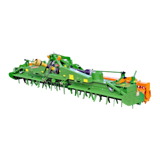
- Page 1 Operating manual Soil tillage implement Rotary cultivator KG 4001-2 KG 5001-2 KG 6001-2 Please read and follow this operating manual before putting the machine into operation. MG4372 BAH0060-5 12.17 Keep it in a safe place for future use!
- Page 2 READING THE INSTRUCTION manual and to adhere to it should not appear to be inconvenient and superfluous as it is not enough to hear from others and to realise that a machine is good, to buy it and to believe that now everything would work by itself.
- Page 3 + 49 (0) 5405 501-234 E-mail: amazone@amazone.de Spare part orders Spare parts lists are freely accessible in the spare parts portal at www.amazone.de. Please send orders to your AMAZONE dealer. Formalities of the operating manual Document number: MG4372 Compilation date: 12.17 ...
- Page 4 Send us your suggestions by fax. AMAZONEN-WERKE H. DREYER GmbH & Co. KG Postfach 51 D-49202 Hasbergen, Germany Tel.: + 49 (0) 5405 501-0 Fax: + 49 (0) 5405 501-234 E-mail: amazone@amazone.de KG 4/5/6001-2 BAH0060-5 12.17...
-
Page 5: Table Of Contents
Table of Contents User information ..................8 Purpose of the document ......................8 Locations in the operating manual ................... 8 Diagrams ..........................8 General safety instructions ................. 9 Obligations and liability ......................9 ... - Page 6 Table of Contents Tractor wheel mark eradicator (optional) ................53 Rollers ........................... 54 5.5.1 Cage roller SW ........................54 5.5.2 Tooth packer roller PW ......................55 5.5.3 Wedge ring roller KW ......................55 ...
- Page 7 Table of Contents 8.8.1 Wedge ring roller ........................99 8.8.2 Tooth packer roller ......................... 99 Transportation ..................100 Use of the implement ................103 10.1 Unfolding/folding the implement booms ................105 ...
-
Page 8: User Information
User information User information The User Information section provides information on use of the operating manual. Purpose of the document This operating manual describes the operation and maintenance of the implement. provides important information on safe and efficient handling of the implement. -
Page 9: General Safety Instructions
General safety instructions General safety instructions This section contains important information on safe operation of the implement. Obligations and liability Comply with the instructions in the operating manual Knowledge of the basic safety information and safety regulations is a basic requirement for safe handling and fault-free implement operation. - Page 10 General safety instructions Risks in handling the implement The implement has been constructed to the state-of-the art and the recognised rules of safety. However, operating the implement may cause risks and restrictions to the health and safety of the user or third parties, ...
-
Page 11: Representation Of Safety Symbols
General safety instructions Representation of safety symbols Safety instructions are indicated by the triangular safety symbol and the highlighted signal word. The signal word (DANGER, WARNING, CAUTION) describes the severity of the risk, and carries the following meaning: DANGER Indicates a direct threat at high risk which will result in death or most serious bodily harm (loss of limbs or long-term harm), should it not be prevented. -
Page 12: Organisational Measures
General safety instructions Organisational measures The operator must provide the necessary personal protective equipment as per the information provided by the manufacturer of the crop protection agent to be used, such as: Safety glasses Protective shoes Chemical-resistant overalls ... -
Page 13: User Training
General safety instructions User training Only those people who have been trained and instructed may work with/on the implement. The operator must clearly specify the responsibilities of the people charged with operation and maintenance work. People being trained may only work with/on the implement under the supervision of an experienced person. -
Page 14: Safety Measures In Normal Operation
General safety instructions Safety measures in normal operation Only operate the implement if all the safety and protection equipment is fully functional. Check the implement at least once a day for visible damage and check the function of the safety and protection equipment. Danger from residual energy Note that there may be residual mechanical, hydraulic, pneumatic and electrical/electronic energy on the implement. -
Page 15: Design Changes
General safety instructions 2.10 Design changes You may make no changes, expansions or modifications to the implement without the authorisation of AMAZONEN-WERKE. This also applies when welding support parts. Any expansion or modification work shall require the written approval of AMAZONEN-WERKE. Only use modification and accessory parts approved by AMAZONEN-WERKE so that the type approval, for example, remains valid in accordance with national and international regulations. -
Page 16: Spare And Wear Parts And Aids
Immediately replace any implement parts which are not in a perfect state. Use only genuine AMAZONE spare and wear parts or the parts cleared by AMAZONEN-WERKE so that the operating permit retains its validity in accordance with national and international regulations. If... -
Page 17: Warning Symbols And Other Labels On The Implement
General safety instructions 2.13 Warning symbols and other labels on the implement Always keep all the warning symbols of the implement clean and in a legible state. Replace illegible warning symbols. You can obtain the warning symbols from your dealer using the order number (e.g. - Page 18 General safety instructions Order number and explanation Warning symbols MD 075 Risk of cutting or severing of fingers/hand through direct contact with moving parts involved in the working process! This hazard can cause the most severe injuries with loss of body parts. ...
- Page 19 General safety instructions MD 079 Risk of materials or foreign objects being flung away from or out of the implement when entering or remaining in the danger area of the implement! These dangers can inflict severe injuries on all parts of the body. ...
- Page 20 General safety instructions MD 084 Risk of crushing the entire body due to standing in the swivel range when implement parts are being lowered. Causes serious, potentially fatal injuries anywhere on the body. It is forbidden to stand in the swivel range of the implement when implement parts are being lowered.
- Page 21 General safety instructions MD 089 Risk of crushing the entire body due to standing under suspended loads or raised implement parts. Causes serious, potentially fatal injuries anywhere on the body. It is forbidden to stand under suspended loads or raised implement parts. ...
- Page 22 General safety instructions MD 096 Danger from escaping high-pressure hydraulic fluid due to leaking hydraulic hose lines. This danger may cause serious injuries, perhaps even resulting in death, if escaping high-pressure hydraulic fluid passes through the skin and into the body. ...
- Page 23 General safety instructions MD 113 Study and observe the instructions for cleaning, servicing and maintaining in the appropriate chapter of the operating manual. MD 119 This symbol indicates the maximum drive speed (1000 rpm) and direction of rotation of the drive shaft on the implement side.
-
Page 24: Positions Of Warning Symbols And Other Labels
General safety instructions 2.13.1 Positions of warning symbols and other labels Warning symbols The following diagrams show the arrangement of the warning symbols on the implement. Fig. 1 Fig. 2 KG 4/5/6001-2 BAH0060-5 12.17... -
Page 25: Dangers In Case Of Non-Observance Of The Safety Instructions
General safety instructions Fig. 3 2.14 Dangers in case of non-observance of the safety instructions Non-compliance with the safety information can pose both a danger to people and also to the environment and implement. can lead to the loss of all warranty claims. In particular, non-compliance with the safety information could pose the following risks: ... -
Page 26: Safety Information For Users
General safety instructions 2.16 Safety information for users WARNING Risk of crushing, cutting, being trapped or drawn in, or impact through inadequate roadworthiness and operational safety. Before starting up the implement and the tractor, always check their traffic and operational safety. 2.16.1 General safety instructions and accident prevention instructions ... - Page 27 General safety instructions Before connecting the implement to or disconnecting the implement from the tractor's three-point hydraulic system, secure the operating lever of the tractor hydraulic system so that unintentional raising or lowering is prevented. When coupling and uncoupling implements, move the support equipment (if available) to the appropriate position (stability).
- Page 28 General safety instructions Use of the implement Before starting work, ensure that you understand all the equipment and actuation elements of the implement and their function. There is no time for this when the implement is already in operation! ...
- Page 29 General safety instructions Comply with the maximum load of the connected implement and the permissible axle and drawbar loads of the tractor. The tractor must guarantee the prescribed brake delay for the loaded vehicle combination (tractor plus connected implement). ...
-
Page 30: Mounted Implements
General safety instructions 2.16.2 Mounted implements When attaching to the three-point linkage, the attachment categories on tractor and implement must be compatible or an adapter must be used! Take note of the manufacturer's instructions. Before attaching implements to or removing them from the three- point suspension, shift the operating equipment to a position in which unintended raising or lowering is impossible. -
Page 31: Hydraulic System
Replace the hydraulic hose lines if they are damaged or worn. Only use original AMAZONE hydraulic hose lines. The hydraulic hose lines should not be used for longer than six years, including any storage time of maximum two years. Even... -
Page 32: Electrical System
General safety instructions 2.16.4 Electrical system When working on the electrical system, always disconnect the battery (negative terminal). Only use the prescribed fuses. If fuses are used that are too highly rated, the electrical system will be destroyed – risk of fire ... - Page 33 General safety instructions Observe the prescribed pipe overlaps for universal joint shafts in transport and working positions. (Read and follow the operating manual from the universal joint shaft manufacturer.) When turning corners, observe the permitted bending and displacement of the universal joint shaft. ...
-
Page 34: Cleaning, Maintenance And Repair
Spare parts must meet at least the specified technical requirements of AMAZONEN-WERKE! This is ensured through the use of original AMAZONE spare parts. KG 4/5/6001-2 BAH0060-5 12.17... -
Page 35: Loading And Unloading
Loading and unloading Loading and unloading The pictogram marks the location at which the lifting gear is to be secured to the implement. DANGER Only attach the lifting gear at the marked location. Do not stand under suspended loads. Fig. 4 CAUTION Always load the implement in folded-out position. -
Page 36: Product Description
Product description Product description This section: provides a comprehensive overview of the implement structure. provides the names of the individual modules and controls. If possible, read this section when actually at the implement. This helps you to understand the implement better. Overview of assembly groups Fig. - Page 37 Product description Fig. 7 (1) Two-gear gearbox (3) Angular gearbox with exchange gear stage (4) Trailing roller (2) Universal joint shaft with overload clutch KG 4/5/6001-2 BAH0060-5 12.17...
-
Page 38: Safety And Protective Equipment
Product description Safety and protective equipment Fig. 8/… Universal joint shaft guard Fig. 8 Fig. 9/… (1) Tool guard plate (2) Levelling board (3) Side panel (4) Roller, trailing The above-mentioned components serve as tool protection; use of the implement without these components is not permitted. -
Page 39: Overview - Supply Lines Between The Tractor And The Implement
Product description Overview – Supply lines between the tractor and the implement Power supply cable Designation Function Plug (7-pin) Road traffic lighting system (optional) Plug for tractor socket Oil cooler fan (optional) Hydraulic hose lines All hydraulic hose lines have handles with coloured markings and a code number or code letter to assign the respective hydraulic function to the pressure line of a tractor control unit! -
Page 40: Transportation Equipment
Product description Transportation equipment Fig. 12/... (1) 2 rear-facing turn indicators (2) 2 reflectors, yellow. (3) 2 brake and rear lights (4) 2 red reflectors (5) 2 rear-facing warning signs (6) 2 side-facing warning signs (not permitted in Germany) Fig. 12 Fig. -
Page 41: Proper Use
Compliance with all the instructions in this operating manual. Execution of inspection and maintenance work. Exclusive use of original AMAZONE spare parts. Other uses to those specified above are forbidden and shall be considered as improper. For any damage resulting from improper use ... -
Page 42: Danger Areas And Danger Points
Product description Danger areas and danger points The danger area is the area around the implement in which people can be caught: by work movements made by the implement and its tools. by materials or foreign bodies thrown out of the implement. ... -
Page 43: Rating Plate And Ce Mark
Product description Rating plate and CE mark The diagram shows the location of the rating plate and the CE mark. The CE mark on the implement indicates compliance with the stipulations of the valid EU directives. The rating plate shows: ... -
Page 44: Technical Data
Product description Technical data Rotary cultivator KG 4001-2 KG 5001-2 KG 6001-2 Working width 4.00 5.00 6.00 Transport width 3.00 3.00 3.00 Attachment category Cat. 3 / Cat. 4N Cat. 3 / Cat. 4N Cat. 3 / Cat. 4N Number of rotors... -
Page 45: Necessary Tractor Equipment
Necessary tractor equipment For the implement to be operated as intended, the tractor must fulfil the following requirements: Implement type Tractor engine power KG 4001-2: from 88 kW (120 bhp) upwards KG 5001-2: from 110 kW (150 bhp) upwards KG 6001-2:... -
Page 46: Gearbox - Transmission Fluids And Filling Quantities
Product description 4.11 Gearbox – Transmission fluids and filling quantities Gear oil for two-gear gearboxes for angular gearboxes Manufacturer Transmission fluid Manufacture Transmission fluid (synthetic oil) (synthetic oil) Mobile Glygoyle 30 SNR 130563 Castrol Tribol 800 / 220 Mobile Glygoyle HE 220 Fuchs... -
Page 47: Spur Gear Trough - Oils And Filling Quantities
Mobilgear 600 XP 460 Shell Omala 460 OMV Gear HST 460 Spur gear trough filling quantities Implement type Total filling quantity (2 spur gear troughs) KG 4001-2 36 litres KG 5001-2 42 litres KG 6001-2 50 litres KG 4/5/6001-2 BAH0060-5 12.17... -
Page 48: Layout And Function
Layout and function Layout and function The implement is used on agricultural land for tilling the soil As a stand-alone machine with trailing roller As part of a cultivation combination (Avant) with trailing roller and mounted seeding rail (PSKW or PSPW) ... -
Page 49: Threaded Cartridge
Layout and function On-grip tines in the forward position have a sifting effect: Coarse particles of soil are transported further than fine particles of soil. The fine earth is concentrated in the lower area of the tilled zone; the large particles of soil remain at the surface and protect against capping. -
Page 50: Attachment Category
Layout and function Attachment category The ball sleeves are tractor accessories. 5.2.1 Coupling elements, tractor mount Cat. 3 Fig. 19/… Designation Upper link pin dia. 31.7 mm Upper link ball sleeve Cat. 3 (tractor accessory) Washer Cat. 3 (6.5 mm thick) Lower link pin dia. -
Page 51: Adapter Frame Cat. 5 (Optional)
Layout and function 5.2.3 Adapter frame Cat. 5 (optional) The adapter frame enables use on the K 700. A special universal joint shaft is required for the drive. Fig. 21/… 1. Adapter frame Cat. 5 Fig. 21 KG 4/5/6001-2 BAH0060-5 12.17... -
Page 52: Three-Point Extension Frame (Optional)
Layout and function Three-point extension frame (optional) The three-point extension frame (Fig. 22/1) is used to: Increase the distance between the tractor and the implement. Secure the wheel mark eradicators. Fig. 22 Three-point extension for rotary cultivators Attachment Fig. -
Page 53: Tractor Wheel Mark Eradicator (Optional)
Layout and function Tractor wheel mark eradicator (optional) Fig. 23 The tractor wheels can leave deep tracks on the field. The three-point extension frame (Fig. 23/1) serves to secure the horizontally and vertically adjustable tractor wheel mark eradicator. Fig. 24 The soil tillage implement can be used with a shallower working depth if the deep tracks are eliminated by the wheel mark eradicators. -
Page 54: Rollers
protect the rotating tools. Only use the rotary cultivator with the rollers specified in the section "Technical Data". Soil tillage implement KG 4001-2 KG 5001-2 KG 6001-2 Cage roller 2x SW 2000-520 2x SW 2500-520 2x SW 3000-520... -
Page 55: Tooth Packer Roller Pw
Layout and function 5.5.2 Tooth packer roller PW PW500 PW600 Field of application Use the tooth packer roller PW on light to heavy soils. Mode of operation The tooth packer roller compacts the soil uniformly over the entire working width. Cleaning Adjustable, carbide-coated scrapers clean the roller. -
Page 56: Drive
Layout and function Two adjuster segments (Fig. 30/3) with integrated springs are used to adjust the cutting rail (Fig. 30/4). During operation, the blades can avoid obstacles in the soil by deflecting upwards. Upon delivery, the cutting rail is adjusted such that the ends of the blades are flush with the edges of the roller. -
Page 57: Gearbox/Tractor Pto Shaft Speed/Tine Speed
Layout and function 5.6.1 Gearbox/tractor PTO shaft speed/tine speed Different soils require that the tine speed be adjusted in order to attain the desired fine seedbed. The implement gearbox makes this adjustment possible. Never select a higher tine speed than is absolutely necessary. If the tine speed is increased, the power requirement and tine wear increase disproportionately. -
Page 58: Oil Cooler (Optional)
Layout and function Oil cooler (optional) The oil cooler (Fig. 34/1) cools the transmission fluid. The transmission fluid flows through an oil filter (Fig. 34/2). The fan in the oil cooler is connected to the tractor socket. Every 20 minutes, the fan changes its direction of rotation for approx. -
Page 59: Electronic Drive Monitor (Optional)
Layout and function 5.10 Electronic drive monitor (optional) If the implement encounters a fixed obstacle, the tool carriers may come to a stop. Overload clutches on the input shafts of the angular gearboxes prevent damage to the gearboxes. If the tool carriers come to a stop, the on-board computer issues an alarm via ... - Page 60 Layout and function The electronic drive monitor is connected to the on-board computer. Solo operation: AMALOG+ Fig. 38 Solo operation: AMADRILL+ Fig. 39 Seeding combination operation: AMATRON+ Fig. 40 KG 4/5/6001-2 BAH0060-5 12.17...
-
Page 61: Tool Tines
Layout and function 5.11 Tool tines Length of the Soil tillage implement Tool tines tool tines KG grip/drag 33 cm KG grip Super 33 cm KG 4000-2 Rotary cultivator KG 5000-2 KG grip Special HD 33 cm KG 6000-2 Potato tines 40 cm Tool tines Tool tines... -
Page 62: Tool Tine Minimum Length
Layout and function 5.11.1 Tool tine minimum length The tool tines are subject to wear. Replace the tines once they reach the minimum length L = 150 mm. before they reach the minimum length when working at great working depths, in order to prevent damage/wear to the tool carriers. -
Page 63: Working Depth Of The Soil Tillage Implement
Layout and function 5.12 Working depth of the soil tillage implement The soil tillage implement is supported by the roller. This ensures that the working depth is precisely maintained. 5.12.1 Mechanical adjustment of the working depth The working depth is adjusted by relocating the depth setting pin (Fig. -
Page 64: Side Panel
Layout and function 5.13 Side panel The side panel (Fig. 50/1) ensures that the tilled soil is guided in front of the roller and not thrown to the side. The swivelling side panel moves over obstacles. The dead weight of the side panel and a tension spring (Fig. -
Page 65: Centre Line Eradicator (Optional)
Layout and function The working height of the levelling board is adjustable. The adjustments must be made evenly across the entire working width. Fig. 53 5.15 Centre line eradicator (optional) For design reasons, the tracks of the tines do not intersect in the centre of the implement. -
Page 66: Combination Possibilities With Other Implements
Layout and function Both track markers (Fig. 56/1) must be raised when turning at the end of the field. Both track markers (Fig. 56/1) must be raised for transporting the implement. The track markers are hydraulically locked. Fig. 56 5.17 Combination possibilities with other implements Fig. -
Page 67: Initial Commissioning
Initial commissioning Initial commissioning This section contains information on initial operation of your implement. on checking how you may couple the implement to your tractor. DANGER Risk of crushing, cutting, being caught or drawn in and knocks! Before starting up the implement and tractor, always check their roadworthiness and operational safety. -
Page 68: Checking The Suitability Of The Tractor
Initial commissioning Checking the suitability of the tractor WARNING Danger of breaking during operation, insufficient stability and insufficient tractor steering and braking power on improper use of the tractor! Check the suitability of your tractor before you attach or hook up the implement. -
Page 69: Calculating The Actual Values For The Total Tractor Weight, Tractor Axle Loads And Load Capacities, As Well As The Minimum Ballast
Initial commissioning 6.1.1 Calculating the actual values for the total tractor weight, tractor axle loads and load capacities, as well as the minimum ballast The permissible total tractor weight, specified in the vehicle documentation, must be greater than the sum of the ... - Page 70 Initial commissioning 6.1.1.1 Data required for the calculation (attached implement) Fig. 58 Tractor empty weight See tractor operating manual or vehicle Front axle load of the empty tractor documentation Rear axle load of the empty tractor Total weight of rear-mounted implement or See section "Technical Data"...
- Page 71 Initial commissioning 6.1.1.2 Calculation of the required minimum ballasting at the front G of the tractor to V min ensure steering capability Enter the numeric value for the calculated minimum ballast G V min required on the front side of the tractor, in the following table.
- Page 72 Initial commissioning 6.1.1.7 Table Actual value according to Approved value Double approved calculation according to tractor load capacity (two operating manual tyres) Minimum ballast front/rear Total weight Front axle load Rear axle load You can find the approved values for the total tractor weight, axle loads and load capacities in the tractor registration papers.
-
Page 73: Securing The Tractor/Implement Against Unintentional Start-Up And Rolling
Initial commissioning Securing the tractor/implement against unintentional start-up and rolling WARNING Risk of crushing, shearing, cutting, being caught and/or drawn in, or impact when making interventions in the implement, through unintentional lowering of the unsecured implement when it is raised via the three-point hydraulic system of the tractor. -
Page 74: Attachment Of The Wheel Mark Eradicators
Initial commissioning Attachment of the wheel mark eradicators 1. Mount the wheel mark eradicators (optional). 1.1 Screw the wheel mark eradicator (Fig. 59/1) to the three-point extension frame using the clamping plate (Fig. 59/2). 1.2 Pin the wheel mark eradicators right at the top with the positioning bolts (Fig. - Page 75 Initial commissioning 4. Attach the roller carrying arm (Fig. 63/1) to the adjuster segment (Fig. 63/2) with a pin (Fig. 63/3). Secure the pin with a screw and nut (Fig. 63/4). 5. Plug the depth setting pin (Fig. 63/5) into the closest possible hole above the carrying arm and secure the depth setting pin using a linch pin (Fig.
-
Page 76: Adjusting The Length Of The Universal Joint Shaft To The Tractor (Specialist Workshop)
Initial commissioning 6.4.1 Adjusting the length of the universal joint shaft to the tractor (specialist workshop) WARNING Only a specialist workshop may make structural changes to the universal joint shaft. WARNING Danger of crushing from unintentional Rolling of the tractor and the coupled implement! ... -
Page 77: Hydraulic Hose Lines
Initial commissioning Hydraulic hose lines WARNING Danger of infection from escaping hydraulic fluid at high pressure! When coupling and uncoupling the hydraulic hose lines, ensure that the hydraulic system is depressurised on both the implement and tractor sides. If you are injured by hydraulic fluid, contact a doctor immediately. 6.5.1 Coupling the hydraulic hose lines Check the compatibility of the hydraulic fluids. -
Page 78: Uncoupling The Hydraulic Hose Lines
Initial commissioning 6.5.2 Uncoupling the hydraulic hose lines 1. Set the tractor control unit to float position (neutral position). 2. Unlock the hydraulic connector. 3. Push on the dust protection caps. Fig. 67 4. Place the hydraulic hose lines in the hose cabinet. -
Page 79: Coupling And Uncoupling The Implement
Coupling and uncoupling the implement Coupling and uncoupling the implement When coupling and uncoupling the implement take heed of the section “Safety information for users”. Danger Secure the tractor and the implement against unintentional start-up and rolling before working on the implement. ... - Page 80 Coupling and uncoupling the implement WARNING Risk of contusions, cutting, catching, drawing in and knocks when the implement unexpectedly releases from the tractor! Use the intended equipment to connect the tractor and the implement in the proper way. When coupling the implement to the tractor's three-point hydraulic system, ensure that the tractor mount categories of the tractor and the implement are the same.
-
Page 81: Coupling The Implement To The Tractor
Coupling and uncoupling the implement Coupling the implement to the tractor Adjust the length of the universal joint shaft to the tractor (see section "Adjusting the universal joint shaft to the tractor") before initial use. after fitting/removing the three-point hitch extension ... - Page 82 Coupling and uncoupling the implement 5. Attach the three-point extension frame (optional, Fig. 71/1) to a crane and secure the rotary cultivator. 6. Secure the pins with linch pins. Fig. 71 7. Secure the implement-side universal joint shaft half on the gearbox input shaft. Observe the operating manual from the universal joint shaft manufacturer.
- Page 83 Coupling and uncoupling the implement 10. Instruct persons to get out of the danger area between the tractor and the implement. 11. Drive the tractor towards the implement, leaving a clearance of approx. 25 cm. The tractor lower links must be flush with the lower hinging points of the implement.
- Page 84 Coupling and uncoupling the implement the implement is at a minimum when the tractor upper link is horizontal. 21. Bring the soil tillage implement into a straight position by adjusting the upper link. 22. Secure the upper link against twisting. 23.
-
Page 85: Uncoupling The Implement
Coupling and uncoupling the implement Uncoupling the implement WARNING Danger of being crushed, cut, caught, drawn in or struck through insufficient stability and possible tilting of the uncoupled implement! Park the implement in a level parking area on solid ground. CAUTION Avoid coming into contact with hot gearbox and universal joint shaft components. - Page 86 Coupling and uncoupling the implement 6. Decouple the lower link hooks, working from the tractor cab. 7. Pull the tractor forward approx. 25 cm. The clearance between tractor and implement provides convenient access for uncoupling the universal joint shaft and supply lines.
-
Page 87: Settings
Settings Settings DANGER Carry out the adjustments only if the following apply: The tractor PTO shaft is disengaged (wait until the tool carriers have come to a complete stop). The implement has been lowered and folded out. The tractor parking brake is applied. -
Page 88: Adjusting The Working Depth Of The Rotary Cultivator
Settings Adjusting the working depth of the rotary cultivator The soil tillage implement is supported by the roller. This ensures that the working depth is precisely maintained. Adjust the following to the new rotary cultivator working depth: side panels ... - Page 89 Settings 6. Position the depth setting pins (Fig. 82/1): In both centre segments. In the same square hole. 7. Secure both positioning rods using linch pins (Fig. 83/3). The adjustments may differ between the inner and outer sections. Make the adjustments so that the rotary cultivator is positioned horizontally with respect to the field surface during the work.
-
Page 90: Hydraulic Adjustment Of The Trailing Roller
Settings 8.1.2 Hydraulic adjustment of the trailing roller Two hydraulic cylinders (Fig. 85/1) are connected to the tractor control unit (beige) for adjusting the working depth. The scale (Fig. 85/3) displays the set working depth. Actuation of the control unit (blue) adjusts the working depth (Fig. - Page 91 Settings 8.1.3.1 Parking the leading tyre packer To prevent swinging of the tyre packer when the implement is folded, it is pegged in the lowest position during transport. 1. Disengage the tractor PTO shaft, engage the tractor parking brake, shut off the tractor engine and remove the ignition key.
-
Page 92: Adjusting The Side Panels
Settings Adjusting the side panels In order to restrict the soil stream effectively, the working depth of the side panels, the working depth of the soil tillage implement, and the spring tension must be adjusted to the soil conditions. Vertical adjustment The side panel is fastened with two round-head screws (Fig. -
Page 93: Adjusting The Tractor Wheel Mark Eradicator
Settings Adjusting the tractor wheel mark eradicator Vertical adjustment Adjust the tractor wheel mark eradicator vertically, position it and secure the positioning bolt (Fig. 89/1) with a linch pin. Horizontal adjustment Adjust the tractor wheel mark eradicator horizontally and secure it with the screws (Fig. 89/2). -
Page 94: Adjusting The Levelling Board
Settings Adjusting the levelling board 1. Attach the extension pipe (Fig. 90/1) to the lever (Fig. 90/2) in reversed position and secure it using the linch pin (Fig. 90/3). Fig. 90 2. Raise the levelling board (Fig. 90/6) to the desired height. -
Page 95: Adjusting The Track Marker
Fig. 93/… Distance from the centre of the implement to the contact area of the track marker disc Working width Distance A KG 4001-2 4.0 m KG 5001-2 5.0 m KG 6001-2 6.0 m Fig. 93 KG 4/5/6001-2 BAH0060-5 12.17... -
Page 96: Setting The Speed Of The Tool Tines
Settings Setting the speed of the tool tines DANGER Carry out the adjustments only with the tractor PTO shaft disengaged, the engine shut off, the tractor parking brake applied and the ignition key removed! Wait until the tool carriers have come to a complete stop. ... -
Page 97: Adjusting The Cutting Rail (Optional, Only With Cracker Disc Roller)
Settings Adjusting the cutting rail (optional, only with cracker disc roller) Two adjuster segments (Fig. 95) with integrated springs (Fig. 95/1) are used to adjust the cutting rail. During operation, the blades can avoid obstacles in the soil by deflecting upwards. Upon delivery, the cutting rail is adjusted such that the ends of the blades are flush with the edges of the roller. -
Page 98: Readjusting Worn Blades
Settings 8.7.2 Readjusting worn blades Always perform the same settings on all adjuster segments. 1. Put the cutting rail in position A (see section "Adjusting the response", page 98). 2. Turn the hexagon nut (Fig. 97/1) on the spring package until the ends of the blades are flush again with the edges of the roller. -
Page 99: Adjusting The Roller Scraper
Settings Adjusting the roller scraper To prevent damage to the roller sleeve, the carbide-coated scrapers must not touch the roller sleeve. 8.8.1 Wedge ring roller 1. Uncouple the seed drill. 2. Using the tractor hydraulics, lift the soil tillage implement just enough for the roller to clear the ground. -
Page 100: Transportation
Transportation Transportation When driving on public streets or roads, the tractor and implement must comply with the national road traffic regulations (in Germany the StVZO and the StVO) and the accident prevention regulations (in Germany those of the industrial injury mutual insurance organisation). In Germany and in many other countries, the maximum transport width of the implement combination mounted on the tractor is 3.0 m. - Page 101 Transportation 1. Instruct any people in the area to stand at a minimum distance of 10.0 m from the implement. 2. Parking the leading tyre packer (see section 8.1.3.1, Seite 91) 3. Fold in the implement booms. Fig. 102 4. Remove the pin, which is secured using a spring cotter pin.
- Page 102 Transportation DANGER Before transportation, carry out a visual check that the upper and lower link pins are secured with the original linch pins against unintentional release. Before transportation, fasten the side locking device of the tractor lower link so that the connected or coupled implement cannot swing back and forth.
-
Page 103: Use Of The Implement
Use of the implement Use of the implement When using the implement, observe the information in the following sections: Warning symbols and other labels on the implement. Safety information for the operator. DANGER Risk of crushing, being pulled in or caught during implement operation because of unprotected drive elements. - Page 104 Use of the implement WARNING Risk of being crushed, caught or struck by objects ejected by the implement when it is driven! Instruct people to leave the danger area of the implement before you switch on the PTO shaft. DANGER ...
-
Page 105: Unfolding/Folding The Implement Booms
Use of the implement 10.1 Unfolding/folding the implement booms DANGER Make sure no persons are in the swivel range of the implement booms before folding the implement booms in and out. Before folding in and out, raise the rotary cultivator so that the tool tines and the roller have sufficient ground clearance. -
Page 106: Unfolding The Implement Booms
Use of the implement 10.1.1 Unfolding the implement booms 1. Raise the tractor lower links. Raise the rotary cultivator. The tool tines and the roller need sufficient ground clearance for folding. 2. Open the bars (Fig. 107/1) by actuating the cables (Fig. - Page 107 Use of the implement DANGER After the booms are folded in, check that both bars (Fig. 109/1) are engaged properly and the cables are relieved. 4. The inner carrying arms lock automatically. The locking element (Fig. 107/1) prevents collision of the distributor heads during sowing rail operation.
-
Page 108: Folding In The Lighting System
Use of the implement 10.2 Folding in the lighting system 1. Before working in the field, fold the booms of the lighting system (see Fig. 112). Fig. 112 2. Position and secure the booms of the lighting system with pins and spring cotter pins. -
Page 109: On The Field
Use of the implement 10.3 On the field DANGER Instruct any people in the area to stand at a minimum distance of 10.0 m from the implement. 10.3.1 Work commencement 1. Unfold the implement booms on the field. 2. Lower the soil tillage implement until the tines are just above, but not yet touching, the soil. - Page 110 Use of the implement The working depth can be adjusted hydraulically during work. Actuation of the control unit ( ) adjusts the beige working depth of the rotary cultivator. Lock the control unit ( ) after each beige adjustment. The scale (Fig. 115/2) displays the set working depth.
-
Page 111: After Use
Use of the implement 10.3.3 After use When switching off the implement, ensure that the soil tillage implement is parked on firm ground. To prevent damage the tines of the wheel mark eradicator should be able to penetrate loose earth. ... - Page 112 Use of the implement 10.3.3.2 Moving the track marker to transport position DANGER Secure the track markers immediately after work on the field (transport lock). Unsecured track markers could unintentionally move to the working position and cause serious injury. Only remove the transport lock for the track marker immediately before beginning field work.
-
Page 113: Faults
Faults Faults WARNING Danger of crushing, shearing, cutting, being caught or drawn in, winding and knocks through: unintentional falling of the implement raised using the tractor's three-point hydraulic system. unintentional lowering of raised, unsecured implement parts. unintentional start-up and rolling of the tractor-implement combination. -
Page 114: Tool Tines Stopping When Work Is In Progress
Faults 11.3 Tool tines stopping when work is in progress If the implement encounters an obstacle, the tool carriers may come to a stop. In order to prevent damage to the gearbox, install overload clutches on the gearbox input shafts of the angular gearboxes. If the tool carriers come to a stop, stop driving and lower the tractor's PTO shaft speed (approx. -
Page 115: Cleaning, Maintenance And Repair
Cleaning, maintenance and repair Cleaning, maintenance and repair 12.1 Safety first WARNING Danger of crushing, shearing, cutting, being caught or drawn in, winding and knocks through: unintentional falling of the implement raised using the tractor's three-point hydraulic system. unintentional lowering of raised, unsecured implement parts. -
Page 116: Cleaning The Implement
Cleaning, maintenance and repair 12.2 Cleaning the implement Pay particular attention to the brake, air and hydraulic hose lines. Never treat brake, air and hydraulic hose lines with fuel, benzene, petroleum or mineral oils. After cleaning, grease the implement, in particular after cleaning with a high pressure cleaner/steam jet or liposoluble agents. -
Page 117: Adjustment Work
Cleaning, maintenance and repair 12.3 Adjustment work 12.3.1 Switching the gear wheels in the two-gear gearbox (specialist workshop) DANGER Secure the tractor and the implement against unintentional start-up and unintentional moving. Avoid coming into contact with hot components and transmission fluids. -
Page 118: Replacing The Tool Tines (Specialist Workshop)
Cleaning, maintenance and repair 12.3.2 Replacing the tool tines (specialist workshop) 1. Fold the implement booms. 2. Check that the two brackets engage correctly when the extension arms are folded in (see section "Folding the implement booms"). 3. Remove the linch pin (Fig. 124/1). 4. -
Page 119: Lubrication Specifications
Cleaning, maintenance and repair 12.4 Lubrication specifications Carefully clean the grease nipple and grease gun before lubrication so that no dirt is pressed into the bearings. Press the dirty grease completely into the bearings and replace it with new grease. The pictogram indicates a lubrication point. -
Page 120: Greasing Points - Overview
Cleaning, maintenance and repair 12.4.2 Greasing points – overview Refer to the table (Fig. 127) for the lubrication points and lubrication intervals. Lubrication points Number of Lubrication interval Please note (see Figure) grease nipples Fig. 128/1 50 h Clean and lubricate the universal joint Fig. -
Page 121: Maintenance Schedule - Overview
Cleaning, maintenance and repair 12.5 Maintenance schedule – overview Carry out maintenance work when the first interval is reached. The times, continuous services or maintenance intervals specified in any third party documentation shall have priority. Check the hydraulic hose lines. Before initial Specialist commissioning... - Page 122 Cleaning, maintenance and repair Checking the upper and lower link Before starting work Section 12.9 pins Check: (daily) Length of the tool tines After completion of work Cleaning the implement (as Section 12.2 required) (daily) Each week Check the hydraulic hose lines. Specialist Section 12.11 The inspection has to be recorded...
-
Page 123: Two-Gear Gearbox
Cleaning, maintenance and repair 12.6 Two-gear gearbox Venting The gearbox is equipped with a ventilation valve (Fig. 132/1). Ventilation must be ensured to prevent the gearbox from developing leaks. Check the oil level 1. Park the implement on a level surface. When the fill quantity is correct, the oil level is visible in the oil sight glass (Fig. -
Page 124: Angular Gearbox
Cleaning, maintenance and repair 12.7 Angular gearbox Venting The dipstick (Fig. 133/1) is equipped with a ventilation valve. Ventilation must be ensured to prevent the gearbox from developing leaks. Check the oil level 1. Park the implement on a level surface. 2. -
Page 125: Spur Gear Trough
Cleaning, maintenance and repair 12.8 Spur gear trough Venting The spur gear trough is equipped with a ventilation pipe (Fig. 134/1). Ventilation must be ensured to prevent the spur gear trough from developing leaks. Check the oil level 1. Park the implement on a level surface. 2. -
Page 126: Changing The Oil Filter In The Cooling Kit (Specialist Workshop)
Cleaning, maintenance and repair 12.8.1 Changing the oil filter in the cooling kit (specialist workshop) 1. Remove the oil filter cartridge (Fig. 135/1). 1.1 Undo the screws (Fig. 135/2). 1.2 Carefully remove the oil filter cartridge. Collect the escaping fluid. 2. -
Page 127: Checking/Cleaning/Lubricating The Ratchet Clutch (Specialist Workshop)
Cleaning, maintenance and repair 12.10 Checking/cleaning/lubricating the ratchet clutch (specialist workshop) When used under normal conditions, the ratchet clutch (Fig. 136/1) is maintenance-free. If the clutch engages frequently, open the ratchet clutch, clean it and lubricate it with special grease (for more information, refer to the maintenance instructions of the universal joint shaft manufacturer). -
Page 128: Hydraulic System
Replace the hydraulic hose lines if they are damaged or worn. Only use original AMAZONE hydraulic hose lines. The hydraulic hose lines should not be used for longer than six years, including any storage time of maximum two years. Even... -
Page 129: 12.11.1 Labelling Of Hydraulic Hose Lines
Cleaning, maintenance and repair 12.11.1 Labelling of hydraulic hose lines The valve chest identification provides the following information: Fig. 137/... (1) Manufacturer's marking on the hydraulic hose line (A1HF) (2) Date of manufacture of the hydraulic hose line (12/02 = year/month = February 2012) (3) Maximum approved operating pressure (210 BAR). -
Page 130: 12.11.4 Installation And Removal Of Hydraulic Hose Lines
12.11.4 Installation and removal of hydraulic hose lines When installing and removing hydraulic hose lines, always observe the following information: Only use original AMAZONE hydraulic hose lines. Ensure cleanliness. You must always install the hydraulic hose lines so that, in all states of operation: ... -
Page 131: Adjusting The Speed Of The Implement Booms During Folding (Specialist Workshop)
Cleaning, maintenance and repair 12.12 Adjusting the speed of the implement booms during folding (specialist workshop) A higher unfolding speed of the rotary cultivator than that set at the factory can cause damage to the implement. Therefore, make a correction only in exceptional cases with sufficient reason. Using a hexagon socket wrench (Fig. -
Page 132: Screw Tightening Torques
Cleaning, maintenance and repair 12.13 Screw tightening torques Observe the specific data for tightening torques in the maintenance section. The table shows the permissible maximum values for bolted connections with a friction coefficient of µ=0.12 and does not include any other safety factors. The listed tightening values are to be considered as reference values! 10.9 12.9... - Page 133 Cleaning, maintenance and repair The specified tightening values represent reference values! 19.3 KG 4/5/6001-2 BAH0060-5 12.17...
- Page 134 +49 5405 501-0 D-49202 Hasbergen-Gaste Fax: +49 5405 501-234 Germany E-mail: amazone@amazone.de http:// www.amazone.de Plants: D-27794 Hude D-04249 Leipzig F-57602 Forbach Branches in England and France Manufacturers of mineral fertiliser spreaders, field sprayers, seed drills, soil tillage implements,...
Need help?
Do you have a question about the KG 4001-2 and is the answer not in the manual?
Questions and answers