Table of Contents
Advertisement
Quick Links
Advertisement
Table of Contents

Related Manuals for Amazone Cenius 3002-T


Summary of Contents for Amazone Cenius 3002-T
- Page 1 Operating Manual Cenius 3002-T Cenius 3502-T Cenius 4002-T Super / Special Mulch cultivator Read and observe this operating manual before using MG4442 the machine for the first time! BAG0097.2 03.12 Printed in Germany Keep it in a safe place for...
- Page 2 Reading the instruc- tion manual and to adhere to it should not appear to be inconvenient and superfluous as it is not enough to hear from others and to realise that a machine is good, to buy it and to believe that now everything would work by itself.
- Page 3 + 49 (0) 5405 501-234 E-mail: amazone@amazone.de Spare part orders Spare parts lists are freely accessible in the spare parts portal at www.amazone.de. Please send orders to your AMAZONE dealer. Formalities of the operating manual Document number: MG4442 Compilation date: 03.12 ...
- Page 4 Send us your suggestions by fax. AMAZONEN-WERKE H. DREYER GmbH & Co. KG Postfach 51 D-49202 Hasbergen Phone: + 49 (0) 5405 50 1-0 Fax: + 49 (0) 5405 501-234 E-mail: amazone@amazone.de Cenius02-T BAG0097.2 03.12...
-
Page 5: Table Of Contents
Table of Contents User information ..................7 Purpose of the document......................7 Locations in the operating manual...................7 Diagrams used .........................7 General safety instructions.................8 Obligations and liability ......................8 Representation of safety symbols..................10 Organisational measures .......................11 Safety and protection equipment ...................11 Informal safety measures.......................11 User training...........................12 Safety measures in normal operation ..................13 Dangers from residual energy....................13... - Page 6 Table of Contents 5.11 Hydraulic connections ......................44 5.11.1 Connecting hydraulic hoses ....................44 5.11.2 Disconnecting hydraulic hoses....................45 Commissioning ..................46 Checking the suitability of the tractor ..................47 6.1.1 Calculating the actual values for the total tractor weight, tractor axle loads and load capacities, as well as the minimum ballast ................
-
Page 7: User Information
User information User information The "User information" section supplies information on using the op- erating manual. Purpose of the document This operating manual Describes the operation and maintenance of the machine. Provides important information on safe and efficient handling of the machine. -
Page 8: General Safety Instructions
General safety instructions General safety instructions This section contains important information on safe operation of the machine. Obligations and liability Comply with the instructions in the operating manual Knowledge of the basic safety information and safety regulations is a basic requirement for safe handling and fault-free machine operation. Obligations of the operator The operator is obliged only to let those people work with/on the ma- chine who... - Page 9 General safety instructions Risks in handling the machine The machine has been constructed to the state-of-the art and the recognised rules of safety. However, there may be risks and restric- tions which occur when operating the machine For the health and safety of the user or third persons, ...
-
Page 10: Representation Of Safety Symbols
General safety instructions Representation of safety symbols Safety instructions are indicated by the triangular safety symbol and the highlighted signal word. The signal word (DANGER, WARNING, CAUTION) describes the gravity of the risk and has the following sig- nificance: DANGER Indicates an immediate high risk, which will result in death or serious physical injury (loss of body parts or long term damage) if not avoided. -
Page 11: Organisational Measures
General safety instructions Organisational measures The operator must provide the necessary personal protective equip- ment, such as: Protective goggles, Safety shoes, Protective overall, Skin protection cream, etc.. The instruction manual Must always be kept at the place at which the machine is operated. -
Page 12: User Training
General safety instructions User training Only trained and instructed persons should be allowed to work with/on the machine. The responsibilities of the operating and maintenance personnel must be clearly defined. People being trained may only work with/on the machine under the supervision of an experienced person. -
Page 13: Safety Measures In Normal Operation
General safety instructions Safety measures in normal operation Only operate the machine if all the safety and protection equipment is fully functional. Check the machine at least once a day for visible damage and check the function of the safety and protection equipment. Dangers from residual energy Note that there may be residual mechanical, hydraulic, pneumatic and electrical/electronic energy at the machine. -
Page 14: Spare And Wear Parts And Aids
Immediately replace any machine parts which are not in a perfect state. Use only genuine AMAZONE spare and wear parts or parts approved by AMAZONEN-WERKEN to ensure that the operating permit retains its validity in accordance with national and international regulations. If... -
Page 15: Warning Pictograms And Other Signs On The Machine
General safety instructions 2.13 Warning pictograms and other signs on the machine 2.13.1 Positioning of warning pictograms and other labels The following diagrams show the arrangement of the warning picto- grams on the machine. Fig. 1 Always keep all the warning pictograms of the machine clean and in a legible state. - Page 16 General safety instructions Warning pictograms - structure Warning pictograms indicate danger areas on the machine and warn of residual dangers. Permanent or unexpected dangers exist in these areas. A warning pictogram consists of two fields: Field 1 is a pictogram describing the danger, surrounded by triangular safety symbol.
- Page 17 General safety instructions Order number and explanation Warning pictograms MD 078 Risk of crushing of fingers/hand by accessi- ble, moving parts of the machine! This danger can cause extremely serious injuries resulting in the loss of limbs. Never reach into the danger area when the trac- tor engine is running with the PTO shaft or hy- draulic/electrical system connected.
- Page 18 General safety instructions MD 082 Danger of falling from treads and platforms when riding on the machine. This danger causes serious or potentially fatal injuries anywhere on the body. It is forbidden to ride on the machine and/or climb the machine while it is running. This also applies to machines with treads or platforms.
- Page 19 General safety instructions MD 100 This symbol indicates attachment points for lifting gear for loading the machine. MD 102 Dangerous situations for the operator due to unintentional starting / rolling of the machine during all work on the machine, e.g. installa- tion, adjustment, troubleshooting, cleaning or maintenance.
-
Page 20: Dangers Of Not Observing Safety Instructions
General safety instructions MD 174 Danger from unintended continued movement of the machine. Causes serious, potentially fatal injuries any- where on the body. Secure the machine against unintended contin- ued movement before uncoupling the machine from the tractor. To do this, use the parking brake and/or the wheel chock(s). -
Page 21: Safety Information For Users
General safety instructions 2.16 Safety information for users WARNING Before starting up the machine and the tractor, always check their traffic and operational safety. 2.16.1 General safety and accident prevention information Beside these instructions, comply with the general valid national safety and accident prevention regulations. - Page 22 General safety instructions Be particularly careful when coupling the machine to the tractor or uncoupling it from the tractor! There are contusion and cutting points in the area of the coupling point between the tractor and the machine. Standing between tractor and implement when the three point hydraulic is actuated is prohibited.
- Page 23 General safety instructions Machine transportation When using public highways, national road traffic regulations must be observed. Before moving off, check: the correct connection of the supply lines the lighting system for damage, function and cleanliness the brake and hydraulic system for visible damage ...
-
Page 24: Hydraulic System
Replace the hydraulic hose line if it is damaged or worn. Only use AMAZONE original hydraulic hose lines. The hydraulic hose lines should not be used for longer than six years, including any storage time of maximum two years. Even... -
Page 25: Electrical System
General safety instructions 2.16.3 Electrical system When working on the electrical system, always disconnect the battery (negative terminal). Only use the prescribed fuses. If fuses are used that are too highly rated, the electrical system will be destroyed – danger of fire! ... -
Page 26: Cleaning, Maintenance And Repairs
Spare parts must meet at least the specified technical require- ments of AMAZONEN-WERKE! This is ensured through the use of AMAZONE original spare parts! Cenius02-T BAG0097.2 03.12... -
Page 27: Loading And Unloading
Loading and unloading Loading and unloading WARNING Risk of crushing due to accidental falling of a machine attached to a load carrier during loading and unloading! Use only slings (ropes, belts, chains, etc.) with a minimum ten- sile strength greater than the total weight of the machine (see Technical data). -
Page 28: Product Description
Product description Product description This section: Provides a comprehensive overview of the machine structure. Provides the names of the individual modules and controls. Read this section when actually at the machine. This helps you to understand the machine better. Overview of subassemblies Fig. -
Page 29: Supply Hoses Between The Tractor And The Machine
Product description Supply hoses between the tractor and the machine Hydraulic hose lines Electric cable for lighting Transportation equipment Fig. 4 (1) Rear lights, brake lights and turn indicators, red rear reflectors (2) Warning signs Fig. 5 (1) Front boundary lights, turn indicators (2) Front warning signs (3) Two side reflectors each, left and right side. -
Page 30: Intended Use
Compliance with all the instructions in this operating manual. Execution of inspection and maintenance work. Exclusive use of AMAZONE original spare parts. Other uses to those specified above are forbidden and shall be con- sidered as improper. For any damage resulting from improper use: ... -
Page 31: Danger Area And Danger Points
Product description Danger area and danger points The danger area is the area around the machine in which people can be caught: By work movements made by the machine and its tools By materials or foreign objects ejected by the machine ... -
Page 32: Rating Plate And Ce Marking
Product description Rating plate and CE marking The following illustration shows the arrangement of the type plate and the CE declaration. The type plate and CE signare located on the frame. The rating plate shows the following information: Machine ID no. ... -
Page 33: Technical Data
Product description Technical data Cenius -T 3002 3502 4002 [mm] 3000 3500 4000 Working width Transport dimensions Width 3000 3500 4000 [mm] Length 6000 6000 6000 [mm] Height 2000 2000 2000 [mm] 3000 3300 3650 [kg] Permissible total weight Permissible axle load 2000 2150... -
Page 34: Necessary Tractor Equipment
Product description Necessary tractor equipment For the machine to be operated as intended, the tractor must fulfil the following requirements: Tractor engine power Cenius 3002-T from 90 kW (120 hp) Cenius 3502-T from 105 kW (140 hp) Cenius 4002-T from 120 kW (160 hp) Electrical system ... -
Page 35: Structure And Function
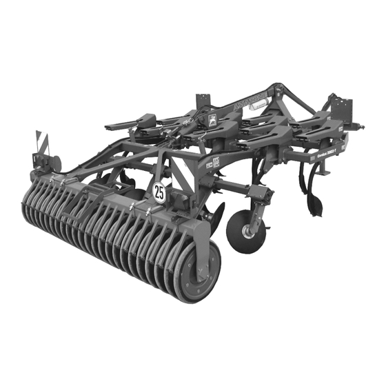
Structure and function Structure and function The following section provides information on the machine structure and the functions of the individual components. Fig. 7 The Cenius mounted disc cultivator is suitable for Stubble processing Non-tilling topsoil processing Seed bed preparation It consists of ... -
Page 36: Tines
Structure and function Tines Cenius Super: Tines with overload protection by two tension springs. The overload protection, which consists of two tension springs, allows the tines to give way if an overload situation occurs. Fig. 8 Cenius Special: Tines with over- load protection by shear bolt. -
Page 37: Coulter
Structure and function Coulter The tines can be fitted with various coulters: Stubble coulter: used to mix in volunteer grain and straw when processing flat stubble. Helix coulter: used for average soil depths; good mixing in of organic matter. ... -
Page 38: Coulter Arrangement
Structure and function Coulter arrangement Cenius 3002 Cenius 3502 Cenius 4002 Fig. 11 The coulter arrangement recommended by the factory is illustrated. However, an individual arrangement is also possible. Cenius02-T BAG0097.2 03.12... -
Page 39: Levelling Unit
Structure and function Levelling unit The following components act as levelling ele- ments: A concave disc arrangement or A spring tine arrangement. The discs mix, crumble and level out the earth. As an alternative to round discs, the machine can also be equipped with serrated discs. -
Page 40: Boundary Discs
Structure and function Boundary discs Extendable boundary discs (Fig. 13) prepare an even field with no lateral banks. As an alternative to round discs, the machine can also be equipped with serrated discs. When transporting the machine, completely slide in both boundary discs / boundary tines, fix with bolts and secure with linch pins. -
Page 41: The Wedge Ring Roller
Structure and function The wedge ring roller The wedge ring roller (Fig. 15/1) compacts the cultivated soil in strips, assumes the depth control of the concave discs. forms the running gear during transport. The scraper bar (Fig. 15/2) cleans between the wedge rings. Fig. -
Page 42: Stand
Structure and function Stand Fig. 17 (1) Handle (2) Pin During operation or transport: Jack fixed in raised position with pin and secured with linch pin. With machine uncoupled: Jack fixed in lowered position with pin and secured with linch pin. Feeler wheels (Option for Cenius 4002-T) The feeler wheels reduce swinging around the longitudinal axis during operation. -
Page 43: Safety Chain For Implements Without Brake System
Structure and function 5.10 Safety chain for implements without brake system Implements without a brake system or with a single-line brake system must be equipped with a safety chain in compliance with local country regulations. The safety chain must be correctly fixed to a suitable position on the tractor before transporting. -
Page 44: Hydraulic Connections
Structure and function 5.11 Hydraulic connections WARNING Danger of infection from escaping hydraulic fluid at high pres- sure! When coupling and uncoupling the hydraulic hose lines, ensure that the hydraulic system is depressurised on both the machine and trac- tor sides. If you are injured by hydraulic fluid, contact a doctor immediately. -
Page 45: Disconnecting Hydraulic Hoses
Structure and function 1. Move the control lever of the spool valve on the tractor to float position (neutral position). 2. Clean the hydraulic connectors of the hydraulic hoses before connecting the hydraulic hoses to the tractor. 3. Connect the hydraulic hoses to the tractor control units. 5.11.2 Disconnecting hydraulic hoses 1. -
Page 46: Commissioning
Commissioning Commissioning This section contains information on operating your machine for the first time. on checking how you may connect the machine to your tractor. Before operating the machine for the first time the operator must have read and understood the operating manual. ... -
Page 47: Checking The Suitability Of The Tractor
Commissioning Checking the suitability of the tractor WARNING Danger of breaking during operation, insufficient stability and insufficient tractor steering and braking power in the event of improper use of the tractor! Check the suitability of your tractor before you attach or hook up the machine. - Page 48 Commissioning 6.1.1.1 Data required for the calculation Fig. 20 [kg] Empty tractor weight See tractor operating manual or vehicle [kg] Front axle load of the empty tractor documentation [kg] Rear axle load of the empty tractor [kg] Total weight rear mounted implement or rear Please see technical rear mounted imple- weight ment or rear weight...
- Page 49 Commissioning 6.1.1.2 Calculation of the required minimum front ballast G of the tractor to ensure safe V min steering Enter the numeric value for the calculated minimum ballast G V min required on the front side of the tractor, in the table (section 6.1.1.7).
- Page 50 Commissioning 6.1.1.7 Table Actual value according to Approved value ac- Double approved calculation cording to tractor load capacity (two instruction manual tyres) Minimum ballast front/rear Total weight Front axle load Rear axle load You can find the approved values for the total tractor weight, axle loads and load capacities in the tractor registration papers.
-
Page 51: Requirements For Tractor Operation With Attached Machines
Commissioning 6.1.2 Requirements for tractor operation with attached machines WARNING Risk of breakage during operation of components through unap- proved combinations of connecting equipment! Ensure: that the connection fittings on the tractor possess sufficient permissible support capability for the drawbar load actually present. -
Page 52: Securing The Tractor/Machine Against Unintentional Start-Up And Rolling
Commissioning Securing the tractor/machine against unintentional start-up and rolling WARNING Risk of crushing, shearing, cutting, catching, drawing in and knocks during all work on the machine By driven work elements. By unintentional movement of work elements or uninten- tional actuation of hydraulic functions when the tractor en- gine is running. -
Page 53: Coupling And Uncoupling The Machine
Coupling and uncoupling the machine Coupling and uncoupling the machine When coupling and uncoupling machines, follow the instructions given in the section "Safety instructions for the operator" page 21. WARNING Risk of crushing, catching, drawing in and/or knocks due to un- intentional starting and rolling of the tractor when coupling or uncoupling the PTO shaft and supply lines. -
Page 54: Coupling The Machine
Coupling and uncoupling the machine Coupling the machine WARNING Risk of crushing and contusions between the tractor and the machine when coupling the machine! Instruct people to leave the danger area between the tractor and the machine before you approach the machine. Any helpers may only act as guides standing next to the tractor and the machine, and may only move between the vehicles when both are at a standstill. - Page 55 Coupling and uncoupling the machine 1. Secure the ball sleeves over the lower link pins in the pivot points of the three-point attachment frame. 2. Secure each of the pins with lynch pins to ensure that they do not accidentally come loose. 3.
-
Page 56: Uncoupling The Machine
Coupling and uncoupling the machine Uncoupling the machine WARNING Risk of contusions, cutting, catching, drawing in and knocks through insufficient stability and possible tilting of the uncou- pled machine! Park the empty machine on a horizontal space with a hard surface. When uncoupling the machine, there must always be enough space in front of the machine, so that you can align the tractor with the ma- chine if necessary. -
Page 57: Adjustments
Adjustments Adjustments WARNING Risk of contusions, cutting, catching, drawing in and knocks through unintentional falling of the machine raised using the trac- tor's three-point hydraulic system. unintentional falling of raised, unsecured machine parts. unintentional start-up and rolling of the tractor-machine combination. -
Page 58: Working Depth Of The Levelling Unit
Adjustments Working depth of the levelling unit The working depth of the levelling unit can be adapted to the working depth of the tines at the cranks. 1. Remove the linch pin (Fig. 22/1). 2. Adjust the working depth at the crank. 3. -
Page 59: Setting The Feeler Wheels
Adjustments Setting the feeler wheels Adjust the feeler wheels height using the group of holes so that they run with a 1-3 cm gap above the ground. 1. Take the eccentric lever out of park posi- tion. 2. Completely insert the pivot pins of the ec- centric lever into a suitable hole in the hole group and release the safety pins. -
Page 60: Transportation
Transportation Transportation DANGER During transportation, follow the instructions given in the section "Safety instructions for the operator", page 24. Before moving off, check: that the supply lines are connected correctly. the lighting system for damage, proper operation and cleanness, ... -
Page 61: Changing From Working To Transport Position
Transportation WARNING Danger of breaking during operation, insufficient stability and insufficient tractor steering and braking power on improper use of the tractor! These risks pose serious injuries or death. Observe the permissible axle and drawbar loads of the tractor. WARNING Risk of falling from the machine if riding against regulations! It is forbidden to ride on the machine and/or climb the running ma- chine. -
Page 62: Use Of The Machine
Use of the machine Use of the machine When using the machine, observe the information in the sections "Warning pictograms and other labels on the machine", from page 16 and "Safety instructions for operators", from page 21 Observing this information is important for your safety. WARNING Danger of breaking during operation, insufficient stability and insufficient tractor steering and braking power on improper use... -
Page 63: Operation
Faults 10.2 Operation The machine is coupled to the tractor. The working depth of the tines and the levelling unit is set. The machine is in working position. Adjust the machine so that the frame stays horizontal. ... -
Page 64: Cleaning, Maintenance And Repairs
Cleaning, maintenance and repairs Cleaning, maintenance and repairs WARNING Risk of contusions, cutting, catching, drawing in and knocks through unintentional falling of the machine raised using the trac- tor's three-point hydraulic system. unintentional falling of raised, unsecured machine parts. ... -
Page 65: Cleaning
Cleaning, maintenance and repairs 12.1 Cleaning Pay particular attention to the brake, air and hydraulic hoses! Never treat brake, air and hydraulic hoses with petrol, benzene, petroleum or mineral oils. After cleaning, grease the machine, in particular after cleaning with a high pressure cleaner/steam jet or liposoluble agents. - Page 66 Cleaning, maintenance and repairs Lubricants For lubrication work, use a lithium saponified multipurpose grease with EP additives: Company Lubricant name Normal operating condi- Extreme operating con- tions ditions ARAL Aralub HL 2 Aralub HLP 2 FINA Marson L2 Marson EPL-2 ESSO Beacon 2 Beacon EP 2...
-
Page 67: Maintenance Plan - Overview
Cleaning, maintenance and repairs 12.3 Maintenance plan - overview Carry out maintenance work when the first interval is reached. The times, running hours or maintenance intervals of any third party documentation shall have priority. After the first working run Component Servicing work Workshop work... -
Page 68: Installing And Removing The Tines
Cleaning, maintenance and repairs 12.4 Installing and removing the tines CAUTION The tines and coulter of the Cenius can be replaced when on the field. For this purpose, slightly raise the machine in order to minimise the risk of injuries by the machine lowering unintentionally. Cenius Special ... -
Page 69: Changing The Vario-Clip Coulters
Cleaning, maintenance and repairs 12.5.1 Changing the Vario-Clip coulters To remove the Vario-Clip coulter (Fig. 29/1), knock the spiral pin (Fig. 29/2) out by knocking it downwards using a drift and remove the coulter towards the front. To install the Vario-Clip coulter, slide it in and secure with the spiral pin. -
Page 70: Replacing Discs (Workshop Work)
Cleaning, maintenance and repairs 12.8 Replacing discs (workshop work) Minimum disc diameter: 360 mm. The discs are replaced the machine lifted, headland setting discs raised, the machine secured against unintentional lowering Fig. 31 12.9 Tine connection Inspect the bolts of the tine connection for tight- ness. -
Page 71: Roller Connection Outside
Cleaning, maintenance and repairs 12.11 Roller connection outside Cenius 3502-T, 4000-T: Inspect the bolts of the tine connection for tight- ness. Required tightening torque: 120 Nm Fig. 34 12.12 Disc carrier connection Inspect the bolts of the tine connection for tight- ness. -
Page 72: Hydraulic System (Workshop Work)
Replace the hydraulic hose line if it is damaged or worn. Only use AMAZONE original hydraulic hose lines. The hydraulic hose lines should not be used for longer than six years, including any storage time of maximum two years. Even... -
Page 73: 12.13.1 Labelling Hydraulic Hose Lines
Cleaning, maintenance and repairs 12.13.1 Labelling hydraulic hose lines The assembly labelling provides the follow- ing information: Fig. 36/... (1) Manufacturer's marking on the hydraulic hose line (A1HF) (2) Date of manufacture of hydraulic hose line (04/02 = year/month = February 2004) (3) Maximum approved operating pressure (210 BAR). -
Page 74: 12.13.4 Installation And Removal Of Hydraulic Hose Lines
12.13.4 Installation and removal of hydraulic hose lines When installing and removing hydraulic hose lines, always observe the following information: Only use AMAZONE original hydraulic hose lines. Ensure cleanliness. You must always install the hydraulic lines so that, in all states of operation: ... -
Page 75: Hydraulic Circuit Diagram
Hydraulic circuit diagram Hydraulic circuit diagram Fig. 37 Cenius02-T BAG0097.2 03.12... -
Page 76: Screw Tightening Torques
Hydraulic circuit diagram 13.1 Screw tightening torques 10.9 12.9 M 8x1 M 10 16 (17) M 10x1 M 12 18 (19) M 12x1,5 M 14 M 14x1,5 M 16 M 16x1,5 M 18 M 18x1,5 M 20 M 20x1,5 M 22 M 22x1,5 1050 M 24... - Page 77 Notes Cenius02-T BAG0097.2 03.12...
- Page 78 Postfach 51 Phone: +49 5405 501-0 D-49202 Hasbergen-Gaste Fax: +49 5405 501-234 Germany e-mail: amazone@amazone.de http:// www.amazone.de Plants: D-27794 Hude D-04249 Leipzig, Germany F-57602 Forbach, France, Branches in England and France Manufacturers of mineral fertiliser spreaders, field sprayers, sowing machines, soil cultivation ma-...
Need help?
Do you have a question about the Cenius 3002-T and is the answer not in the manual?
Questions and answers