
Related Manuals for Futech AMPCLAMP 200


Summary of Contents for Futech AMPCLAMP 200
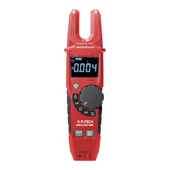
- Page 1 USER MANUAL EN ENGLISH 430.200 AMPCLAMP 200 Manual in your language? Check the back cover...
- Page 2 OVERVIEW —...
-
Page 3: Lcd Display
HOUSING LCD DISPLAY 01 NCV tutpoints Alternating voltage / current (AC) 02 Current fork Minus sign 03 Non-contact voltage indicator Direct voltage / current (DC) 04 LCD display D Auto power off 05 Selector light Auto range mode 06 Rotary function selector Continuity symbol 07 Function list with backlight G Diode symbol... -
Page 4: Operation
SAFETY OPERATION Please read the safety instructions provided as AC CURRENT MEASUREMENTS separate booklet with the device. Do not exceed the maximum allowed input · Turn the rotary function selector [06] to the range of any function (e.g. circuit whose voltage position “200A”. - Page 5 VOLTAGE MEASUREMENTS (AC OR DC) Capacitive coupling between wires make it ap- pear that non-powered wires are connected to a · Insert the black test probe [15] into the Neg- real source of voltage. ative/COM probe connector [13] and the red test probe [15] into the positive probe connec- The Low Z setting places a load on the circuit.
-
Page 6: Resistance Measurements
RESISTANCE MEASUREMENTS · If the measured resistance is at less than 50 Ohm, a tone will sound. · Insert the black test probe [15] into the Neg- ative/COM probe connector [13] and the red CAPACITANCE MEASUREMENTS test probe [15] into the positive probe connec- ·... -
Page 7: Diode Measurements
DIODE MEASUREMENTS BLACK PROBE PROBE · Insert the black test probe [15] into the Neg- ative/COM probe connector [13] and the red test probe [15] into the positive probe connec- Forward Test tor [14]. BLACK · Turn the rotary function selector [06] to the PROBE PROBE position “Ohm –... -
Page 8: Max/Min Button
DATA HOLD & FLASHLIGHT BUTTON [08] EXTRA BUTTONS · In case you are measuring in a position where MODE & LCD BACKLIGHT BUTTON [09] you have no direct view on the LCD Display [04], press the Data Hold / Flashlight button ·... -
Page 9: Automatic Power Off
AUTOMATIC POWER OFF After cleaning, do not use the voltage tester for approx. 5 hours. In order to save battery life, this device will automatically switch off after approximately 15 BATTERY REPLACEMENT minutes. If no signal sound is audible when short-circuit- ·... -
Page 10: Specifications
SPECIFICATIONS ACCURACY FUNCTION RANGE RESOLUTION ±(% OF READIING + DIGITS) AC Current 200.A 100mA ±(3% + 5 digits) Over rang protection: Maximum input 200A; Frequency response: 50 to 60Hz 1000V - 6000V ±(1.2% + 5 digits) AC True RMS 60.00V 10mV Voltage ±1.2% + 2 digits) 600.0V 100mV (Auto sense) 1000V ±(1.5% + 2 digits) Input impedace: 10M Ω; Low input impedance test voltage: ~3KΩ MAX 600V AC;... - Page 11 ACCURACY FUNCTION RANGE RESOLUTION ±(% OF READIING + DIGITS) Resistance 600.0 Ω 0.1 Ω ±(1.% + 4 digits) 6.000k Ω 1 Ω 60.00K Ω 10 Ω ±(1.5% + 4 digits) 600.0K Ω 100 Ω 6.000M Ω 1K Ω ±(2.5% + 4 digits) 60.00M Ω 10K Ω ±(3.5% + 4 digits) Over rang protection: 300V rms Capacitance 60.00nF 0.01nF...
-
Page 12: General Specifications
GENERAL SPECIFICATIONS 430.200 AMPCLAMP Clamp size 0.6” (16mm) approx. Display (6000 counts) LCD display Continuity check Buzzer sounds < 50� Diode test Test current of 3.35mA typical; Open circuit voltage <3VDC typical Measurement rate 3 readings / Second Input impedance ~10M� (VDC & VAC) Low input impedance ~3k� (VDC and VAC) Operating temperature 5 - 40°C (41 - 104°F) - Page 13 DECLARATION OF CONFORMITY Futech (Belgium) declares under its own responsibility that this device: - 430.200 AMPCLAMP 200 is in conformity with the standards - EN 61326-1:2013 - EN 61326-2-1:2013 Under Electromagnetic Compatibility (EMC) Directive 2014/30/EU Lier, Belgium, December 22, 2023 Patrick Waûters...
- Page 14 NOTES...
- Page 15 NOTES...
- Page 16 USER MANUAL other languages: DANSK ITALIANO DEUTSCH NEDERLANDS ESPAÑOL NORSK EESTI KEEL PORTUGUÊS SUOMEN KIELI SL SLOVENŠČINA FRANÇAIS SVENSKA ÍSLENSKA Facebook @futechtools LinkedIn futechtools World Wide Web futech-tools.com YouTube @futechtools...
Need help?
Do you have a question about the AMPCLAMP 200 and is the answer not in the manual?
Questions and answers