Advertisement
Quick Links
INSTRUCTION MANUAL [EN]
570.15S – Drill Pointer 2
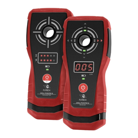
DESCRIPTION
1. Marking aid opening
2. Power button
3. LED indicator for metal detection
4. LED indicator for ac voltage detection
5. Power indicator
6. Marking aid opening
7. Power button
8. Red arrow/green rectangle LED indicator
9. Display
10. Power indicator
SAFETY
Please read the complete safety instructions in the booklet delivered with this device.
FIRST USE
Remove protective films where applied.
To differentiate the transmitter and the receiver, look at the lowest side of the front of both devices.
The name of the device is found there. The receiver can be distinguished too since it is the one of
both devices having a LED display.
POWER
Type of battery for receiver: 3 x 1.5V AAA batteries
Type of battery for transmitter: 3 x 1.5V AAA batteries
When the power indicator on the transmitter or receiver flashes, the battery power is not high
enough and must be replaced.
Before battery replacement, make sure the device is turned off. Remove the screw on the battery
cover and remove the cover. Replace the batteries with new ones of the same type. Make sure the
polarity connections are correct! Reinstall the battery cover and the screw.
MANUAL 570.15S - DRILL POINTER 2 [EN]
TRANSMITTER
1
3
4
5
2
RECEIVER
8
6
9
10
7
V1.0 – 10.2022
1
Advertisement

Subscribe to Our Youtube Channel
Related Manuals for Futech Drill Pointer 2


Summary of Contents for Futech Drill Pointer 2
- Page 1 Before battery replacement, make sure the device is turned off. Remove the screw on the battery cover and remove the cover. Replace the batteries with new ones of the same type. Make sure the polarity connections are correct! Reinstall the battery cover and the screw. MANUAL 570.15S - DRILL POINTER 2 [EN] V1.0 – 10.2022...
- Page 2 Before drilling on wall or ceiling, make sure there are no cables, pipes, metallic objects or other objects on and near the drilling path. The receiver must always be positioned parallel to the transmitter. MANUAL 570.15S - DRILL POINTER 2 [EN] V1.0 – 10.2022...
- Page 3 If you briefly press the power key again or switch off the receiver, the receiver will revert to normal operating mode. · Location of drill bit exit point of oblique hole MANUAL 570.15S - DRILL POINTER 2 [EN] V1.0 – 10.2022...
- Page 4 Metal objects deeper than the transmitter detection limit from wall surface will not be detected. · Detection Live AC Wire The transmitter can be used to detect live ac wire directly beneath plaster or behind wooden panel or non-metal paneling. MANUAL 570.15S - DRILL POINTER 2 [EN] V1.0 – 10.2022...
-
Page 5: Maintenance
Frequency band: 1 ISM band: 433.95 MHz Bandwidth: 0.05 MHz Receiver category: 3 Power supply 3x 1.5V Alkaline AAA Size 178 x 75 x 30 mm Weight About 256g (including batteries) MANUAL 570.15S - DRILL POINTER 2 [EN] V1.0 – 10.2022... - Page 6 Bandwidth: 0.05 MHz Receiver category: 3 Power supply 3x 1.5V Alkaline AAA Size 178 x 75 x 30 mm Weight About 256g (including batteries) (* @ temperature 21°C, wall thickness 200mm) MANUAL 570.15S - DRILL POINTER 2 [EN] V1.0 – 10.2022...
Need help?
Do you have a question about the Drill Pointer 2 and is the answer not in the manual?
Questions and answers