Table of Contents
Advertisement
Quick Links
Advertisement
Table of Contents

Related Manuals for Compliance West MegaPulse Antenna Surge PF 65


Summary of Contents for Compliance West MegaPulse Antenna Surge PF 65
- Page 1 MegaPulse IMPULSE TESTER Antenna Surge PF 65 Instruction Manual...
- Page 2 To fully appreciate all the features of your new instrument, we suggest that you take a few moments to review this manual. Compliance West USA stands by your instrument with a full one-year warranty. If the need arises, please don't hesitate to call on us.
-
Page 4: Table Of Contents
Table of Contents An Introduction to Impulse Testing with the MegaPulse P series tester .............2 Safety Precautions ........................2 Test Personnel ........................2 Testing Area ........................2 Safety Techniques ......................3 Using the MegaPulse Impulse Tester ...................3 Introduction ..............................5 Specifications ..........................5 Operation ..............................7 Setting up your Tester ........................7 AC Line Voltage Requirements....................7 Fuse Replacement.........................8 Front and Rear Panel Features ......................8... -
Page 6: An Introduction To Impulse Testing With The Megapulse P Series Tester
Section 1 An Introduction to Impulse Testing with the MegaPulse PF series tester The impulse test is designed to simulate impulse surges which occur in everyday life due to nearby lightning strikes, switching transients, and other high-frequency faults on the power distribution network. -
Page 7: Safety Techniques
Safety Techniques The high voltage circuit of the MegaPulse Antenna Surge PF can be shut off at any time by turning OFF the rear power switch. Always press TRIGGER to discharge the tester before turning OFF. The MegaPulse tester is provided with a digital VOLTAGE ADJUST knob on the front panel. This voltage setting should always confirm by pressing the VOLTAGE ADJUST knob before start any testing. - Page 8 Pressing the POLARITY switch on the front panel will not change the polarity on the Antenna Surge PF, only positive pulses can be performed, the high voltage will appear on the OUTPUT as a positive pulse relative to the RETURN jack. Note that the voltage meter may indicate that some residual voltage is present on the main storage capacitor, even when the tester is first turned ON.
-
Page 9: Introduction
Section 2 Introduction This manual contains complete operating, maintenance and calibration information for the Compliance West USA MegaPulse Antenna Surge PF Impulse Tester. In case of trouble, the test can be immediately terminated at any time by turning the rear- •... - Page 10 Table 2. Load Option Switch. Standard Load Option Switch Position 60065 IEC, paragraph 10.1 No Load UL60950-1 Annex N, Table N.1, Line 3 No Load EN 60065:1993 , Fig 7a, sub-clause14.2 performed on a component comprising a capacitor only. 4M OHM LOAD *NOTE: C1 is being charged at a higher voltage to compensate the loss experienced when the switch is turned to the ON position (Trigger), this due to the small capacitor of 1nF which starts discharging during the transition...
-
Page 11: Operation
Your Tester is shipped in a special protective container that should prevent damage to the instrument during shipping. Check the shipping order against the contents of the container and report any damage or short shipment to Compliance West USA. The container should include the following: The MegaPulse Antenna Surge PF Tester •... -
Page 12: Fuse Replacement
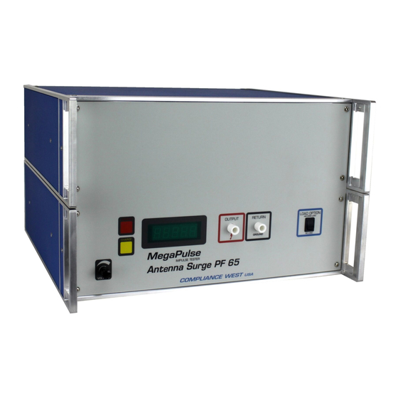
Fuse Replacement There is a user-replaceable fuse (F1) located on the rear panel of the instrument. It is located behind a door in the Power Inlet-Power Switch-Fuse Holder device. The fuse rating is noted on the rear panel. Do not attempt to replace it with a fuse of any other rating. Use the following procedure to replace the fuse F1: 1. - Page 13 Figure 2. Controls, Indicators, Connectors – MegaPulse Antenna Surge PF Front Panel.
- Page 14 Table 3. Controls, Indicators, Connectors – MegaPulse Antenna Surge PF Front Panel. ITEM NAME FUNCTION Adjust the digital voltage set point in the tester. VOLTAGE Adjust Knob Press the voltage knob to display the voltage set point. This setting will blink for a few seconds on the front meter. Turn Clockwise to increase the setting Voltage Setting Point before pressing CHARGE button.
- Page 15 Figure 3. Controls, Indicators, Connectors – MegaPulse Antenna Surge PF Rear Panel. Table 4. Control, Indicators, Connectors – MegaPulse Antenna Surge PF Rear Panel. ITEM NO. NAME FUNCTION Appliance Inlet / Fuse holder Use supplied cordset to connect the MegaPulse Antenna Surge PF tester to an appropriate source of supply. / Power Switch Fuse holder provides access for Fuse replacement, and the Power Switch is used to turn the tester ON and OFF.
-
Page 16: Initial Checkout Procedure
Initial Checkout Procedure The following procedure will verify that the MegaPulse Antenna Surge PF tester is working correctly. We recommend that this procedure be conducted periodically to ensure proper operation of the tester. The following items are needed to conduct this procedure: A measuring instrument to monitor the output waveform. -
Page 17: Testing
Figure 4. Waveform Measurement Setup Testing This section describes how the MegaPulse Antenna Surge PF tester is used to conduct a test. The test can be stopped immediately at any time by turning OFF the rear-panel power switch. Connect the tester to a proper source of supply using the included 18 AWG power supply cord. Plug the Output and Return test leads into the jacks on the front panel. -
Page 18: Manually Enabling The Front Panel Buttons And Disabling The Voltage Stop
Manually Enabling the Front Panel Buttons and Disabling the Voltage Stop If the MegaPulse Antenna Surge PF is displaying “OFF” on the meter when the front buttons are pressed, it means that the front panel buttons have been disabled via the TestMinder software interface. It is possible to enable them manually using the next sequence: Note: Enabling the front panel buttons manually will disable the voltage stop setting. -
Page 19: Technical Assistance
Section 4 Technical Assistance Technical Assistance from Compliance West USA is available: Phone: (800) 748-6224 Hours: 8:00 AM - 4:00 PM Pacific Time. Also available on our web site at: www.compwest.com Contact: Compliance West USA 650 Gateway Center Way, Suite D San Diego, CA., 92102... -
Page 20: Maintenance And Calibration
Section 5 Maintenance and Calibration WARNING MAINTENANCE AND CALIBRATION INSTRUCTIONS ARE FOR QUALIFIED PERSONNEL ONLY. TO AVOID ELECTRIC SHOCK, DO NOT PERFORM ANY SERVICING OTHER THAN CONTAINED OPERATING INSTRUCTIONS. Introduction This section of the manual contains maintenance information for the MegaPulse Antenna Surge PF impulse tester. -
Page 21: Calibration Information
The calibration procedure should be performed at an ambient temperature of 23°C ±5°C (73.4°F ±9°F). The procedure consists on internal components tolerance verification and calibrating the meter reading to agree with the capacitor bank. The Calibration procedure must be performed by qualified personnel, for more information contact Compliance West USA.
Need help?
Do you have a question about the MegaPulse Antenna Surge PF 65 and is the answer not in the manual?
Questions and answers