Table of Contents

Related Manuals for Sorel HIU Controller HCC Fresh


Summary of Contents for Sorel HIU Controller HCC Fresh
- Page 1 HIU Controller HCC Fresh Weather-compensated heating circuit controller with fresh water function for heat interface units Installation and operating instructions Read carefully before installation, commissioning and operation...
- Page 2 CONTENT CAN bus ID Sensor send interval 8.8 Menu Lock Safety Instructions EU-Conformity 9.9 Service Values General Instructions 10.10 Language Explanation of Symbols Changes to the Unit Function overview Warranty and Liability Disposal and Pollutants Heating Circuit (X) Operating Mode Description HCC Fresh S/W Day S/W Night...
-
Page 3: Table Of Contents
Support Guideline Appendix Signal Output Signal PWM / 0-10V off PWM / 0-10V on PWM / 0-10V max. Speed when „On“ Example for signal settings Technical data PWM and 0-10V Show signal Final Declaration... - Page 4 Safety Instructions EU-Conformity By affixing the CE mark to the unit the manufacturer declares that the HCC Fresh conforms to the following relevant safety regulations: EU low voltage directive 2014/35/EU EU electromagnetic compatibility directive 2014/30/EU conforms. Conformity has been verified and the corresponding documentation and the EU declaration of conformity are kept on file by the manufacturer.
- Page 5 Changes to the Unit Changes, additions to or conversion of the unit are not permitted without written permission from the manufacturer. It is likewise forbidden to install additional components that have not been tested together with the unit. If it becomes clear that safe operation of the unit is no longer possible, for example because of damage to the housing, turn the Unit off immediately.
- Page 6 Description HCC Fresh Technical Data Electrical specifications: 100 - 240VAC , 50 - 60 Hz Power Supply 0.5 - 2.5 W / 0.5 Power consumption / standby 2 A slow 250V Internal fuse Protection Class IP40 Protection class / overvoltage category II / II Inputs/Outputs 5 (+ 3 with additional box) Pt1000...
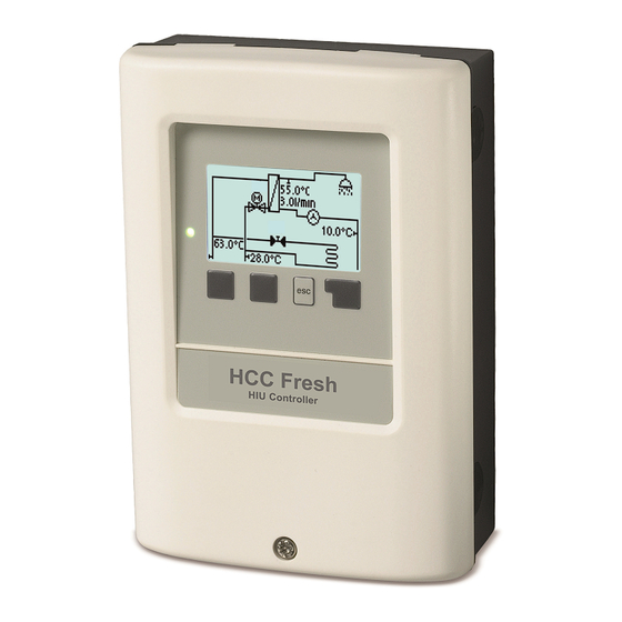
- Page 7 About the Controller The Heating controller with fresh water function HCC Fresh facilitates efficient use and function control of your Heat interface units possible while its handling is intuitive. After every input step the suitable functions are matched to the keys and explained in a text above. In the menu 'measurement values and settings' are help text and graphics in addition to key words.
- Page 8 Hydraulic Variants The following illustrations should be regarded only as schematic representations of the respective hydraulic systems and do not claim to be complete. Under no cir- cumstances should the controller replace any safety devices. Depending on the specific application, additional system and safety components such as check valves, non-return valves, safety temperature limiters, scalding protectors, etc., may be required.
- Page 9 Installation Electrical Terminal Program 1 - without heating circuit Low voltages Mains voltages max. 24 VAC / DC 230 VAC 50 - 60 Hz The sensor ground (S1-S5) is connected to the terminal block Sensor -. Low voltages Mains voltages max.
- Page 10 Electrical Terminals For high-efficiency pumps with 0-10V / PWM signal input, the power can be provided (V1 parallel operation) over a free relay. The connection of the ground wire is made at the lower gray terminal block. The neutral conductor N is connected to terminal block N.
- Page 11 7. Fit the upper part of the housing and insert the other two screws. 8. Align the housing and tighten the three screws. If problems occur with the operation of the terminals, our video on our YouTube page can help you: http://www.sorel.de/youtube...
- Page 12 Electrical Connection Before working on the unit, switch off the power supply and secure it against being switched on again! Check that there is no power flowing! Electrical connections may only be made by a specialist and in compliance with the applicable regulations. The unit may not be put into operation if there is visible damage to the housing, e.g.
- Page 13 Operation Display and Input The display‘s (1), extensive text and graphical mode, enables simple, almost self-explanatory, operation of the controller. Entries are made using 4 keys (3+4), to which contextual functions are assigned. The ‚esc‘ key (3) is used to cancel an entry or to exit a menu.
- Page 14 Commissioning help 1. Set language and time 2. Commissioning help / setup wizard a) select or b) skip. The setup wizard guides through the necessary basic settings in the correct order. Every parameter is explained on the display of the controller. Pressing the “esc” key takes you back to the previous setting.
- Page 15 2.2 Statistics Serve for function control and long-term monitoring of the system. For time-dependent functions such as circulation and anti-legionella and the evaluation of system data, it is essential that the time is accur- ately set on the controller. Please note that the clock continues to run for about 24 hours if the mains voltage is interrupted, and afterward must be reset.
- Page 16 3.3 Release Times Settings for time, date and operating times for the heating circuit. The associated temperature reference values are spe- cified in Menu 5, ‚Settings‘. Time & Date Serve to set the current time and date. For time-dependent functions such as circulation and anti-legionella and the evaluation of system data, it is essential that the time is accurately set on the controller.
- Page 17 4.4 Operating Mode To specify the operating modes for the heating circuit. After an interruption of the mains voltage, the controller automatically returns to the last operating mode selec- ted. Manual The individual relay outputs, v outputs and the connected consumers can be checked for proper functioning and correct assignment. The operating mode ‚Manual‘...
- Page 18 Seizing Protection If the anti-seizing protection is activated (daily, weekly, off), the controller switches the outputs on/off at 12:00 noon for 5 seconds to prevent seizing of the pump/valve after long periods of inactivity. Frost Protection If the temperature at the external sensor falls below 1 °C, the heating circuit is automatically switched on with frost protection activated and the set flow temperature is set to the minimum flow temperature set under See "...
- Page 19 7.7 Special Functions Used to set basic items and expanded functions. The settings in this menu should only be changed by a specialist. Program selection Here the hydraulic variation fitting to the respective use case is selected and set. The program selection normally occurs only once during the first entry into service by a specialist. An incorrect program selec- tion may lead to unpredictable errors.
- Page 20 level. 100% is the maximum possible power of the controller. Min. Speed The minimum speed of the pump is determined here. During the setting, the pump runs in the respective speed and the flow can be determ- ined. The specified percentages are variables, which may deviate more or less strongly depending on the system, pump and pump level.
- Page 21 Network If necessary, the network settings of the connected data logger must be set. CAN bus ID Here you can see the ID of the controller on the CAN bus. Sensor send interval The send interval determines how often the sensor and output values of the controller may be send via CAN. If a value changes, it is sent and starts the interval.
- Page 22 Function overview When assigning relays with functions, the activated function for already used relays must first be deactivated before a new func- tion can be selected. Heating Circuit (X) Operating Mode Heating: automatic/normal operation taking into account operating times (day, comfort increase, night reduction). Reference: fixed flow temperature independent of the outside temperature.
- Page 23 If ‚split is selected, the curve is set in the following steps: 1. Outdoor temperature for slope change 2. Slope over outdoor temperature for change 3. Slope below outdoor temperature for change While setting the slope, the controller also shows the slope value and the calculated target flow temperature at -12 °C as a reference point. In case of repeated adjustment of the split curve, the settings appear in reverse order.
- Page 24 Heat request is started when the flow temperature is continuously below reference temperature for 1 minute. Reference/Actual + This value determines the acceptable underflow of the heating circuit temperature beyond the calculated reference flow temperature at the buffer sensor or flow sensor. If the temperature at the buffer sensor exceeds the reference flow temperature by the value set here, the heating request is deactivated.
- Page 25 In combination with the %-value set under "room controller", the difference between reference and actual room temperature influences the reference flow temperature. If the room controller is set to 0 %, this function is deactivated. For °CALEON room controller without influence. Room Reference Night The desired room temperature for night mode.
- Page 26 Hot Water Tmax Maximum temperature at the hot water sensor. If the maximum temperature at the hot water sensor is exceeded, the drinking water valve is closed. If the temperature falls below the set tem- perature, the valve is released again. Temperature values which are set too high can lead to scalding or damage to the system.
- Page 27 Circulation pause time In order to prevent an excessive switching on of the circulation pump, a block time can additionally be set up here to prevent it from being turned on again. If the circulation pump has turned off, it can first go into operation again after the expiration of the time set here.
- Page 28 Parallel operation Here you can additionally set the switch mode. On : The function switches parallel to the set signal output. Inverted : The function switches contrary to the set signal output. Parallel to Here, the output can be selected, which this function should be activated parallel to. Every available signal output can be selected. Delay In this menu, it is set how long to wait after switching the signal output until the parallel operated relay switches as well.
- Page 29 Malfunctions/Maintenance Replacing the Fuse Repairs and maintenance may only be performed by a specialist. Before working on the unit, switch off the power supply and secure it against being switched on again! Check that there is no power flowing! Only use the supplied spare fuse or a fuse of the same design with the following specifications: 2 AT/250 V. If the mains voltage is switched on and the controller still does not function or display anything, then the internal device fuse may be defective.
- Page 30 Additional Information External relay at signal output V(X) (0-10V / PWM) With the help of an external relay (art. no. 77502), a 0-10V/PWM output V(X) (V1, V2) can be used to obtain a switching capacity of 230 VAC (I) or a potential-free change-over contact (II). The external relay is then activated via the signal output (0V = "off"...
-
Page 31: Support Guideline
If there are errors with your device, please proceed as follows: 1. Read user manual 2. Check FAQ 3. Watch help-video on YouTube 4. Talk to an installation technician/tradesman 5. Contact SOREL Support - provide the following information: What is the Problem? Installation problem New problem Change request Controller Type/Controller Name (9.1.) -
Page 32: Appendix
Appendix Signal In this menu, the preset profiles for the signal can be selected or under “manual” all settings can be done personally. The settings can still be changed after a profile has been selected. Output Signal In this menu the type of actors are set: heating pumps have the greatest output with a small input signal, solar pumps in contrast have very little output with a small input signal. -
Page 33: Technical Data Pwm And 0-10V
Technical data PWM and 0-10V Show signal Represents the set signal in a graphic and text overview. -
Page 34: Final Declaration
Date and time of installation: Name of installation company: Space for notes: Your specialist dealer: Manufacturer: SOREL GmbH Mikroelektronik Reme-Str. 12 D - 58300 Wetter (Ruhr) +49 (0)2335 682 77 0 +49 (0)2335 682 77 10 info@sorel.de www.sorel.de...
Need help?
Do you have a question about the HIU Controller HCC Fresh and is the answer not in the manual?
Questions and answers