
Related Manuals for Sorel FWC3


Summary of Contents for Sorel FWC3
- Page 1 Fresh Water Controller FWC3 Installation and operating instructions Read carefully before installation, commissioning and operation...
-
Page 2: Table Of Contents
Contents A.1. - EC declaration of conformity 5. - Settings A.2. - General instructions 5.1. - Tsetpoint A.3. - Explanation of symbols 5.2. - Tmax A.4. - Changes to the unit 5.3. - VFS -Type A.5. - Warranty and liability 5.4. -
Page 3: Ec Declaration Of Conformity
Safety instructions A.1. - EC declaration of conformity By affi xing the CE mark to the unit the manufacturer declares that the FWC3 conforms to the following relevant safety regulations: EC low voltage directive 73/23/EEC, as amended by 93/68/EEC EC electromagnetic compatibility directive 89/336/EEC version 92/31/EEC version 93/68/EEC Conformity has been verifi... -
Page 4: Changes To The Unit
Safety instructions A.4. - Changes to the unit Changes to the unit can compromise the safety and function of the unit or the entire system. Danger - Changes, additions to or conversion of the unit are not permitted without the written permis- sion from the manufacturer - It is likewise forbidden to install additional components that have not been tested together with the unit... -
Page 5: Specifi Cations
Description of controller B.1. - Specifi cations Electrical specifi cations: Mains voltage 230VAC +/- 10% Mains frequency 50...60Hz Power consumption Switched power Electronic relay R1 min.20W...max.120W for AC3 Mechanical relay R2 460VA for AC1 / 185W for AC3 Internal fuse 2A slow blow 250V Protection category IP40... -
Page 6: About The Controller
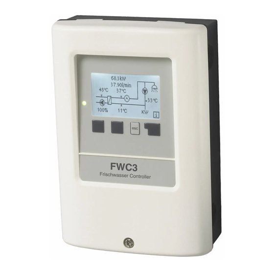
Description of controller B.3. - About the controller The Fresh water controller FWC3 facilitates effi cient use and function control of your fresh water system. The device is impressive most of all for its functionality and simple, almost self-explanatory operation. For each step in the input process the individual entry keys are assigned to appropriate functions and explained. -
Page 7: Hydraulic Variants
Description of controller B.6. - Hydraulic variants The following illustrations should be viewed only as schematic diagrams showing the respective hydraulic systems, and do not claim to be complete. The controller Caution does not replace safety devices under any circumstances. Depending on the spe- cifi... -
Page 8: Wall Installation
Installation C.1. - Wall installation Install the controller only in dry areas and under the ambient conditions descri- bed under 2.1 “Specifi cations”. Carry out the following steps 1-8. Caution 1.Unscrew cover screw completely Fig.C.1.1 2.Carefully pull upper part of housing from lower part. -
Page 9: Electrical Connection
Installation C.2. - Electrical connection Before working on the unit, switch off the power supply and secure it against being switched on again! Check for the absence of power! Electrical connections may Danger only be made by a specialist and in compliance with the applicable regulations. Do not use the controller if the housing shows visible damage. -
Page 10: Terminal Connection Diagrams
Installation D. - Terminal connection diagrams D.1. - „Without circulation pump“ Mains side Sensor side 230VAC max. 12V Danger Caution Low voltage max. 12VAC/DC Mains voltages 230VAC 50-60Hz connection in the left-hand terminal Connection in the right-hand terminal compartment! compartment! Terminal: Connection for: Terminal: Connection for:... -
Page 11: With Circulation Pump
Installation D.2. - „With circulation pump“ Mains side Sensor side 230VAC max. 12V Danger Caution Low voltage max. 12VAC/DC Mains voltages 230VAC 50-60Hz connection in the left-hand terminal Connection in the right-hand terminal compartment! compartment! Terminal: Connection for: Terminal: Connection for: PT1000 cold water Mains phase conductor L PT 1000 circulation... -
Page 12: Display And Input
E. - Operation E.1. - Display and input The display (1), with its extensive text and graphics mode, is almost selfexplanatory, allowing easy opera- tion of the controller. The LED (2) lights up green when a relay is switched The LED (2) lights up red when operating mode “Off”... -
Page 13: Commissioning Help
Parametrisation E.2. - Commissioning help The fi rst time the controller is turned on and after the language and time are set, a query appears as to whether you want to parame- trise the controller using the commissioning help or not. The commissioning help can also be terminated or called up again at any time in the special functions menu. -
Page 14: Menu Sequence And Menu Structure
Operation E.4. - Menu sequence and menu structure The graphics or overview mode appears when no key has been press for 2 minutes, or when the main menu is exited by pressing “esc“. Pressing a key in graphics or overview mode takes you directly to the main menu. -
Page 15: Measurement Values
Measurement values 1. - Measurement values The menu “1. Measurement values” serves to dis- play the currently measured temperatures. The menu is closed by pressing “esc” or selecting “Exit measurement values”. Selecting “Info” leads to a brief help text explaining the measurement values. -
Page 16: Statistics
Statistics 2. - Statistics The menu “2. Statistics” is used for function control and long-term monitoring of the system. The submenus described under 7.1-7.6 are available. The menu is closed by pressing “esc” or selecting “Exit statistics”. For system data statistics it is essential for the time to be set accurately on the control- ler. -
Page 17: Display Mode
Display Mode 3. - Display mode Menu “3. Display mode” is used to defi ne the control- ler’s display for normal operation. This display appears whenever two minutes go by without any key being pressed. The main menu appears again when a key is pressed. -
Page 18: Operating Mode
Operating modes 4. - Operating mode In menu “4. Operating modes” the controller can either be placed in automatic mode, switched off, or placed in a manual operating mode. The menu is closed by pressing “esc” or selecting “Exit operating modes”. 4.1. -
Page 19: Settings
5.1. - Tset Setpoint at sensor 5 The controller FWC3 attempts to maintain a constant temperature at sensor 5 by controlling the speed of the hot water pump. Settings range: 30 ° C to 90 ° C / Default: 45 ° C 5.2. -
Page 20: Circulation
Settings 5.4. - Circulation Mode of circulation Set the mode of circulation in this menu. In mode “Off” a circulation pump is not part of the design (see 2.5 Fig.1). When the mode “Request” is active, the circulation pump is switched on after a correspond- ing withdrawal of water has occured (see 5.5 to 5.8 for instructions to the necessary settings). -
Page 21: Circ. Tmin
Settings 5.7. - Circ. Tmin. Minimum temperature at sensor S2 If the temperature drops below Circ.Tmin at sensor 2 and the circulation is enabled (see „5.10. - Circulation period“), the circulation pump is started. Settings range: 10 ° C to 85 ° C / Default : 30 ° C 5.8. -
Page 22: Special Functions
Special functions 6. - Special functions Menu “6. Special functions” is used to set basic items and expanded functions. Other than the time all settings may only be made by a specialist. Caution The menu is closed by pressing “esc” or selecting “Exit special functions”. -
Page 23: Antilegionella
Special functions 6.5. - Antilegionella With the AL-function activated, the FWC3 3 makes it possible to heat the storage in selectable intervals, (AL interval) for the set residence time (AL resid. time), starting at the set time (AL start time) until the temperature AL Tset is reached. The temperature measured at S5 has a reference of AL Tset +5°. -
Page 24: Speed Control
Special functions 6.6. - Speed control If the speed control is activated, the FWC3 makes it possible to vary the speed of standard pumps at relay R1 by means of special internal electronics. This should only be activated and set up by a specialist! Wrong settings can damage the system! Refer to the pump and system manufacturer’s manuals. -
Page 25: Menu Lock
Menu lock 7. - Menu lock Menu “7. Menu lock” can be used to secure the control- ler against unintentional changing of the set values. The menu is closed by pressing “esc” or selecting “Exit menu lock”. The menus listed below remain completely accessible despite the menu lock being activated, and can be used to make adjustments if necessary: 1. -
Page 26: Service Values
Service values 8. - Service values The menu “8. Service values” can be used for remote diagnosis by a specialist or the manufacturer in the event of an error, etc. Enter the values at the time when the error occurs e.g. in the table. Caution The menu can be closed at any time by pressing “esc”. -
Page 27: Language
Language 9. - Language Menu “9. Language” can be used to select the language for the menu guidance. This is queried automatically during initial commissioning. The choice of languages may differ, however, depend- ing on the device design. Language selection is not available in every device design! -
Page 28: Malfunctions With Error Messages
Malfunctions Z.1 Malfunctions with error messages If the controller detects a malfunction, the red light fl ashes and the warning symbol also appears in the display. If the error is no longer present, the warning symbol changes to an info symbol and the red light no longer fl... -
Page 29: Replacing The Fuse
Malfunctions Z.2 Replacing the fuse Repairs and maintenance may only be performed by a specialist. Before working on the unit, switch off the power supply and secure it against being switched on again! Check for the absence of power! Danger Only use the supplied spare fuse or a fuse of the same design with the following specifi... - Page 30 Maintenance Z.3. Maintenance In the course of the general annual maintenance of your heating system you should also have the functions of the controller checked by a specialist and have the settings optimised if necessary. Caution Performing maintenance: - Check the date and time (see 11.1) - Assess/check plausibility of analyses (see 7.) - Check the error memory (see 7.5) - Verify/check plausibility of the current measurement values (see 6.)
- Page 31 Notes...
- Page 32 Although these instructions have been created with the greatest possible care, the possibility of incorrect or incomplete information cannot be excluded. Subject as a basic principle to errors and technical changes. Manufacturer: SOREL GmbH Mikroelektronik Jahnstr. 36 D - 45549 Sprockhövel Tel.
Need help?
Do you have a question about the FWC3 and is the answer not in the manual?
Questions and answers