
Related Manuals for Sorel SFWC


Summary of Contents for Sorel SFWC
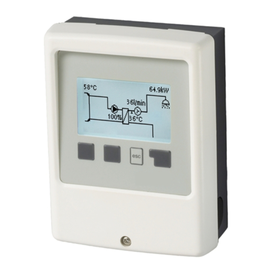
- Page 1 Fresh Water Controller SFWC Installation and instruction manual Read carefully before installation, commissioning and operation...
-
Page 2: Table Of Contents
Factory Settings Warranty and Liability Time & Date Disposal and Pollutants Daylight saving time Specifications Eco Display Mode Temperature unit Description SFWC About the Controller 7. Menu Lock Scope of Supply 8. Service Values Hydraulic Variants 9. Language Installation Wall Installation... -
Page 3: Safety Instructions
Safety Instructions EU-Conformity By affixing the CE mark to the unit the manufacturer declares that the SFWC conforms to the following relevant safety regulations: EU low voltage directive 2014/35/EU EU electromagnetic compatibility directive 2014/30/EU conforms. Conformity has been verified and the corresponding documentation and the EU declaration of conformity are kept on file by the manufacturer. -
Page 4: Warranty And Liability
Warranty and Liability The Unit has been manufactured and tested with regard to high quality and safety requirements. The warranty and liability shall not include, however, any injury to persons or material damage that is attributable to one or more of the following causes: Failure to observe these installation and operating instructions. -
Page 5: Description Sfwc
About the Controller The xxx SFWC facilitates efficient use and function control of your Fresh water system possible while its handling is intuitive. After every input step the suitable functions are matched to the keys and explained in a text above. In the menu 'measurement values and settings' are help text and graphics in addition to key words. -
Page 6: Installation
8. Align the housing and tighten the three screws. If problems occur with the operation of the terminals, our video on our YouTube page can help you: http://www.sorel.de/youtube Electrical Connection Before working on the unit, switch off the power supply and secure it against being switched on again! Check that there is no power flowing! Electrical connections may only be made by a specialist and in compliance with the applicable regulations. -
Page 7: Installing The Temperature Sensors
Installing the Temperature Sensors The controller operates with Pt1000 temperature sensors which are accurate to 1 °C, ensuring optimal control of system functions. If desired, the sensor cables can be extended to a maximum of 30 m using a cable with a cross-section of at least 0.75 mm². -
Page 8: Operation
Operation Display and Input The display‘s (1), extensive text and graphical mode, enables simple, almost self-explanatory, operation of the controller. The function of the other 3 keys (4) is shown in the display right above the keys. The right-hand key generally has a confirmation and selection function. -
Page 9: Measurement Values
Calibration procedure: During the callibration process a text is shown that the flow rate is measured and no tapping is allowed. After confirmation the cir- culation pump is switched off and the controller is waiting until the flow rate has dropped to 0 L/min. Afterwards only the circulation pump is switched on and after another 60 seconds the flow rate is measured. -
Page 10: Operating Mode
3. Operating mode Auto The automatic mode is the normal mode of the controller. A correct controller function under consideration of the current temperatures and the set parameters is only present in automatic mode! After an interruption of the mains voltage, the controller automatically returns to the last operating mode selected. -
Page 11: Settings
Tset Setpoint temperature at the flow sensor. The SFWC controller operates on the condition that the hot water temperature/tap temperature measured at the flow sensor is adjus- ted as quickly as possible and kept constant. Temperature values which are set too high can lead to scalding or damage to the system. Scalding protection must be... -
Page 12: Protective Functions
5. Protective Functions The 'Protective functions‘ can be used by specialists to activate and set various pro- tective functions. By no means does the controller replace the safety appliances on site! Anti Legionella The anti-legionella function is an additional function for certain relay functions such as: electric heating rod, burner, cir- culation, compressor. -
Page 13: Seizing Protection
When the storage sensor is connected: If the temperature at the storage sensor is smaller than Tset -5°C, the target temperature is lowered to the currently measured storage temperature -5°C. In both cases, Circ. Tmin is set to the new setpoint - Circ. Hysteresis -5 K. Here too, the newly calculated value for Circ. Tmin will not be lower than 0 °C, and not higher than the set circ. -
Page 14: Max. Speed
Max. Speed The maximum speed of the pump is determined here in %. During the setting, the pump runs in the respective speed and the flow can be determined. The specified percentages are variables, which may deviate more or less strongly depending on the system, pump and pump level. -
Page 15: Times
Times Here the desired periods are set in which the circulation is approved. For each weekday, three times can be specified, furthermore, you can copy individual day to other days. The circulation is shut down outside of the set times. Tap support To ensure a constant temperature even with small amount of tap water, the circulation pump can be used as support pump. -
Page 16: Menu Lock
7. Menu Lock Secure the controller against unintentional changing and compromise of basic func- tions. Menu lock active = "On" Menu lock off = "Off" In addition, the "Simple" menu view can be used to hide menu items that are not necessary for the daily use of the controller after commissioning. -
Page 17: Malfunctions/Maintenance
Malfunctions/Maintenance Replacing the Fuse Repairs and maintenance may only be performed by a specialist. Before working on the unit, switch off the power supply and secure it against being switched on again! Check that there is no power flowing! Only use the included safeguard or a similar safeguard with the following specifications: T2A / 250 V. -
Page 18: Final Declaration
Date and time of installation: Name of installation company: Space for notes: Your specialist dealer: Manufacturer: SOREL GmbH Mikroelektronik Reme-Str. 12 D - 58300 Wetter (Ruhr) +49 (0)2335 682 77 0 +49 (0)2335 682 77 10 info@sorel.de www.sorel.de...
Need help?
Do you have a question about the SFWC and is the answer not in the manual?
Questions and answers