Sorel CALEONbox Installation And Operating Instruction
Heating circuit controller for surface heating systems
Hide thumbs
Also See for CALEONbox:
- Installation and operating instruction (20 pages) ,
- System instruction (71 pages)

Related Manuals for Sorel CALEONbox


Summary of Contents for Sorel CALEONbox
- Page 1 °CALEONbox Heating circuit controller for surface heating systems Installation and operating instruction Read carefully before installation, commissioning and operatio...
-
Page 2: Table Of Contents
CONTENT Safety Instructions EU-Conformity General instructions Explanation of Symbols Changes to the Unit Warranty and Liability Disposal and Pollutants Description °CALEONbox Description Specifications Scope of Supply Installation Wall Installation Electrical Connection Electrical Terminals LED status Connection Examples Room Controller Connection example apartment building... -
Page 3: Safety Instructions
Safety Instructions EU-Conformity By affixing the CE mark to the unit the manufacturer declares that the°CALEONbox conforms to the following relevant safety reg- ulations: EU low voltage directive 2014/35/EU EU electromagnetic compatibility directive 2014/30/EU EU RoHS Directive 2011/65/EU EU WEEE Directive 2012/19/EU (Reg.nr. DE 23479719) conforms. -
Page 4: Changes To The Unit
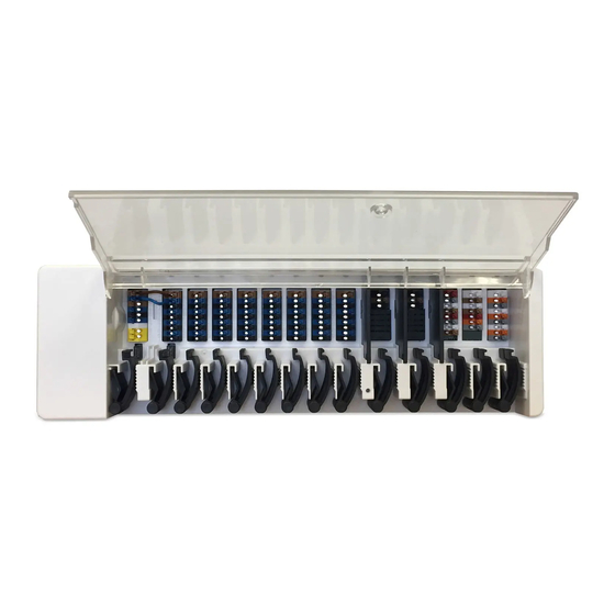
Description The °CALEONbox is a universal heating and individual room controller for surface heating systems. In combination with up to 8 °CALEON Room Controllers, this enables efficient use and function control of your surface heating with intuitive operation. The inputs and outputs can be freely assigned via °CALEON, so that different heating systems can be implemented. -
Page 5: Specifications
Specifications Model °CALEONbox Heating circuit controller for surface heating systems Temperature controller class (ErP) Energy efficiency (ErP) Standby loss 0,5 W Request type invertible heat "On /off" and/or "modulating" pump Electrical specifications: Power supply 230 VAC (+/- 5%), 50 - 60 Hz... -
Page 6: Scope Of Supply
Wall Installation Fix the DIN rail horizontally to the wall using screws. Installation 1. Place the °CALEONbox on the upper edge of the DIN rail with the locking catch on top. 2 Engage the device by pressing it down. Ensure that the locking catches engage completely and that the device is firmly seated on the rail. -
Page 7: Electrical Connection
Electrical Connection Low-voltage cables such as temperature sensor cables must be routed separately from mains voltage cables. Before working on the unit, switch off the power supply and secure it against being switched on again! Check that there is no power flowing! Electrical connections may only be made by a specialist and in compliance with the applicable regulations. -
Page 8: Electrical Terminals
Electrical Terminals 24 VDC CAN high ----- CAN low ----- CAN high CAN high CAN low CAN low 24 VDC CAN high CAN low Example Wiring of Terminal Blocks Mains connection heating circuit pump Actuators for the heating zones Potential-free switching contacts for additional functions °CALEON Room Controller in private CAN bus... -
Page 9: Led Status
Building CAN bus and 1-Wire sensors 0-10V/PWM outputs for additional functions LED status LED A Flashes, if mains voltage is present and relay A is not switched Lights up, if mains voltage is present and relay A is switched. LED B - K Lights up, if relay B - K is switched. -
Page 10: Connection Examples Room Controller
Connection Examples Room Controller Example 1: Tree Structure A 120 Ohm terminating resistor must be set on the first and last device in the CAN network. Example 2: Line A 120 Ohm terminating resistor must be set on the first and last device in the CAN network. -
Page 11: Connection Example Apartment Building
Connection example apartment building Example: °CALEONboxes connected with LHCC controller A 120 Ohm terminating resistor must be set on the first and last device in the CAN network. -
Page 12: Connection Examples 1-Wire Sensors
The 1-Wire ID can be found in the device housing and in the device menu under: Devices -> °CALEONbox -> Resources -> 1-Wire sensor. Example 1: Line. The installation leads from one sensor to the next. A twisted pair cable must be used for the connecting cable. -
Page 13: 1-Wire Id Overview
1-Wire ID overview For systems with 1-Wire sensors, you must assign the respective 1-Wire ID to a room on the °CALEON Room Controller. Writing down the IDs in combination with the room in which the sensor hangs in the following list simplifies the later assignment. -
Page 14: Setup Wizard
The setup wizard is restarted via the "Factory settings" menu item. Operation To configure the °CALEONbox, you need at least one °CALEON Room Controller. This is connected to the °CALEONbox through the private CAN bus as described before (See " Electrical Connection " on page 7). -
Page 15: Operating Mode
Operating Mode Overview > Operating Mode Menu Overview > Operating Mode > Menu... -
Page 16: Set Operation Hours
Set Operation Hours Overview > Operating Mode > Menu > Timer Setting of individual heating times for the selected room. Set Operation Hours In the interests of efficient and energy-saving single room control, the operating times should be set specifically for each room. -
Page 17: Expert Menu
Expert Menu Overview > Operating Mode > Menu > Expert... -
Page 18: Settings
The menu structure described here is based on the status at the time of production and may vary due to subsequent soft- ware changes. Settings Overview > Operating Mode > Menu > Expert > Settings... -
Page 19: Devices
Devices Overview > Operating mode > Menu > Expert > Settings > Devices Overview > Operating mode > Menu > Expert > Settings > Devices > °CALEONbox... -
Page 20: Rooms
Rooms Overview > Operating mode > Menu > Expert > Settings > Rooms Overview > Operating mode > Menu > Expert > Settings > Room 2... -
Page 21: Temperature/Humidity
Temperature/Humidity Overview > Operating mode > Menu > Expert > Settings > Rooms > Room 1 > Temperature Overview > Operating mode > Menu > Expert > Settings > Rooms > Room 1 > Humidity... -
Page 22: Functions °Cbox
Overview > Operating mode > Menu > Expert > Settings > Functions °Cbox Activating and setting of additional functions on the free outputs of the °CALEONbox. Overview > Operating mode > Menu > Expert > Settings > Functions °Cbox > Thermostat 2 Switches the defined output to the set room / rooms depending on time and temperature. - Page 23 Overview > Operating mode > Menu > Expert > Settings > Functions °Cbox > Hc Mixer The heating circuit mixer function controls the flow temperature via a 0-10V / PWM mixer depending on the outdoor tem- perature.
- Page 24 Overview > Operating mode > Menu > Expert > Settings > Functions °Cbox > Heating Circuit The heating circuit function starts the heating pump at the defined output as soon as at least one zone is active.
- Page 25 Overview > Operating mode > Menu > Expert > Settings > Functions °Cbox > Difference The difference function switches the defined output as soon as there is a preset temperature difference between the source and target sensor.
- Page 26 Overview > Operating mode > Menu > Expert > Settings > Functions °Cbox > Timer 2 The function Timer 2 switches the defined output depending on the set times. Overview > Operating mode > Menu > Expert > Settings > Functions °Cbox > Energy request The function energy request switches the defined output when the rooms require energy depending on the set delay.
-
Page 27: Zones
Zones verview > Operating mode > Menu > Expert > Settings > Zones Overview > Operating Mode > Menu > Expert > Settings > Zones > Zone B... -
Page 28: Example Zone Setting
Example zone setting... -
Page 29: Wifi
WiFi Overview > Operating mode > Menu > Expert > Settings > WiFI This menu is only present, if a °CALEON Smart or °CALEON Clima Smart is connected. -
Page 30: Service Values
Service Values Overview > Operating mode > Menu > Expert > Service values... -
Page 31: Caleon Wifi And App Configuration
Provides the option to update °CALEONs and °CALEONboxes in the network to the latest via WiFi (°CALEON Smart only) version. °CALEONbox: Menu > Expert > Settings > Devices > °CALEONbox > Firmware See " Devices " on page 19 °CALEON Room Controller: Menu > Expert > Service Values > Firmware, Download and install update on each °CALEON. - Page 32 Although this list and description have been created with the greatest possible care, incorrect or incomplete information cannot be excluded. Subject as a basic principle to errors and technical changes. SOREL GmbH Mikroelektronik - Reme-Str. 12 - D - 58300 Wetter (Ruhr) - +49 (0)2335 682 77 0 - +49 (0)2335 682 77 10 - info@sorel.de - www.sorel.de...
Need help?
Do you have a question about the CALEONbox and is the answer not in the manual?
Questions and answers