
Related Manuals for Sorel HCC 3


Summary of Contents for Sorel HCC 3
- Page 1 Heating-Controller HCC 3 Weathercontrolled heat circuit regulator Installation and operating instructions Read carefully before installation, commissioning and operation...
-
Page 2: Table Of Contents
Table of content Chapter Page Chapter Page Safety instructions Settings HC Menu 5 10.1 Su/Wi Day 1.1 EC conformity 1.2 General instructions 10.2 Su/Wi Night 1.3 Explanation of symbols 10.3 Curve 1.4 Changes 10.4 Day correction 10.5 Night correction 1.5 Warranty 10.6 Comfort boost Description of controller 2.1 Specifi... -
Page 3: Safety Instructions
Safety instructions 1.1 EC declaration of conformity By affi xing the CE mark to the unit the manufacturer declares that the HCC3 conforms to the following relevant safety regulations: EC low voltage directive 73/23/EEC, as amended by 93/68/EEC EC electromagnetic compatibility directive 89/336/EEC version 92/31/EEC version 93/68/EEC Conformity has been verifi... -
Page 4: Changes
Safety instructions 1.4 Changes to the unit Changes to the unit can compromise the safety and function of the unit or the entire system. Gefahr - Changes, additions to or conversion of the unit are not permitted without written permission from the manufacturer - It is likewise forbidden to install additional components that have not been tested together with the unit - If it becomes clear that safe operation of the unit is no longer possible,... -
Page 5: Description Of Controller
Description of controller 2.1 Specifi cations Electrical specifi cations: Mains Voltage 230VAC +/- 10% Mains frequency 50...60Hz Power consumption Total switched power 460VA (Relay outputs 1-3) Switched power per relay 460VA for AC1 / 185W for AC3 Internal fuse 2A slow blow 250V Protection category IP40 Protection class... -
Page 6: About The Controller
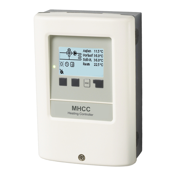
Description of controller 2.2 About the controller The weather controlled Heat Circuit Controller HCC 3 facilitates effi cient use and function control of your heating system. The device is impressive most of all for its functionality and simple, almost self-explanatory operation. -
Page 7: Hydraulic Variants
Description of controller 2.5 Hydraulic variants The following illustrations should be viewed only as schematic diagrams showing the respective hydraulic systems, and do not claim to be complete. The controller does not replace safety devices Caution under any circumstances. Depending on the specifi c application, additional system components and safety components may be mandatory, such as check valves, non-return valves, safety temperature limiters, scalding protectors, etc., and must therefore be provided. -
Page 8: Installation
Installation 3.1 Wall installation Install the controller only in dry areas and under the ambient conditions described under 2.1 „Specifi cations“. Carry out the following steps 1-8. Caution 1. Unscrew cover screw completely Fig.3.1.1 2. Carefully pull upper part of housing from lower part. -
Page 9: Electrical Connection
Installation 3.2 Electrical connection Before working on the unit, switch off the power supply and secure it against being switched on again! Check for the absence of power! Danger Electrical connections may only be made by a specialist and in compliance with the applicable regulations. - Page 10 Installation 3.2.2 Electrical terminals Right-hand terminal compart- Left-hand terminal compart- ment only for mains voltages ment only for low voltage if Danger of 230VAC 50-60Hz max. 12VAC/DC Caution Low voltage max. 12VAC/DC Mains Voltage 230VAC 50-60Hz connection in the left-hand terminal connection in the right-hand terminal compartment! compartment.
-
Page 11: Installing The Sensors
Installation 3.3 Installing the temperature sensors The controller operates with Pt1000 temperature sensors which are accurate to the degree, thus ensuring optimal control of system functions. If desired the sensor cables can be extended to a maximum of 30m using a cable with a cross-section of at least 0.75mm². Make sure that there is no contact resistance! Caution Position the sensor precisely in the area to be measured! -
Page 12: Operation
Operation 4.1 Display and input The display (1), with its extensive text and graphics mode, is almost self-explanatory, allowing easy operation of the controller. The LED (2) lights up green when a relay is switched on. The LED (2) lights up red when operating mode „Off“... -
Page 13: Menu Sequence
Operation 4.2 Menu sequence and menu structure The graphics or overview mode ap- pears when no key has been pressed for 2 minutes, or when the main menu is exited by pressing „esc“. Pressing a key in graphics or overview mode takes you directly to the main menu. -
Page 14: Parametrisation
Parametrisation 5.1 Commissioning help The fi rst time the controller is turned on and after the language and time are set, a query appears as to whether you want to parametrise the controller using the commissioning help or not. The commissioning help can also be terminated or called up again at any time in the special functions menu. -
Page 15: Measurement Values Menu
Measurement values Menu 1 Measurement values Menu “1. Measurement values” serves to display the currently mea- sured temperatures. The menu is closed by pressing “esc” or selecting “Exit measurement values”. Selecting “Info” leads to a brief help text explaining the measurement values. -
Page 16: Statistics Menu
Statistics Menu 2 7. Statistics Menu “2. Statistics” is used for func- tion control and long-term monitoring of the system. The submenus described under 7.1- 7.5 are available. The menu is closed by pressing “esc” or selecting “Exit statistics”. For system data statistics it is essential for the time to be set accurately on the controller. -
Page 17: Time & Date
Times Menu 3 8. Times Menu “3. Times” is used to set the time, date, operating times for the heating circuit and hot water. The associated temperature reference values are speci- fi ed in menu 5 “Settings”! Caution The menu is closed by pressing “esc”... -
Page 18: 8.4 Heat Circuit Day
Operating modes Menu 4 9. Operating modes Menu “4. Operating modes” is used to specify the operating modes for the heating circuit. After an interruption of the mains voltage the controller automatically returns to the last operating mode selected! The menu is closed by pressing “esc”... -
Page 19: Operating Modes Menu
Operating modes Menu 4 9. Operating modes (continued) 9.3 Manual Menu 4.2 In Manual mode the individual relay outputs and the connected consumers can be checked for proper functioning and correct assignment. The operating mode “Manual” may only be used by specialists for brief function tests, e.g. -
Page 20: Settings Hc
Settings Heating circuit Menu 5 10. Settings HC The necessary basic settings required for the control function of the heating circuit are made in menu “5. Settings HC”. This does not under any circumstances replace the safety facilities to be provided Caution by the customer! The menu is closed by pressing... - Page 21 Settings Heat circuit Menu 5 10. Settings HC (continued) = Slope of the characteristic heating curve 10.3 Curve Menu 5.3 The characteristic curve is used to control the heat dissipation of the heating circuit relative to the outdoor temperature. The demand for heat is different due to differences in the type of building/ insulation/type of heating/outdoor temperature.
-
Page 22: Day Correction
Settings Heat circuit Menu 5 10. Settings HC (continued) The following settings can be used for parallel translation of the characteristic for certain time periods such as daytime and nighttime mode. Caution = parallel translation of the characteristic 10.4 Day correction Menu 5.4 The day correction produces a parallel translation of the heating characteristic during the daytime operating hours, since depending on the... -
Page 23: Protective Functions
Protective functions Menu 6 Protective functions Menu “6. Protective functions” can be used by specialists to activate and set various protective functions. This does not under any circumstances replace the safety facilities to be provided Caution by the customer! The menu is closed by pressing “esc”... -
Page 24: Max. Fl Ow
Protective functions Menu 6 11. Protective functions (continued) 11.3 max. fl ow Menu 6.3 This is used as the upper limit for the reference fl ow temperature of the heat circuit. Should the heat circuit temperature exceed this value, the heat circuit is switched off until the temperature drops below. -
Page 25: Special Functions Menu
Special functions Menu 8 12. Special functions Menu “7. Special functions” is used to set basic items and expanded functions. The settings in this menu should only be made by a specialist. Caution The menu is closed by pressing “esc” or selecting “Exit special func- tions”. -
Page 26: Expansions
Special functions Menu 8 12.4 Expansions Menu 7.4 This menu can only be selected and used if additional options or expansion modules have been built into the controller. The associated supplementary installation, mounting and operation instructions are then included with the specifi c expansion. 12.5 Mixer Menu 7.5 Settings are only necessary at the time of initial commissioning by the... -
Page 27: Room Controller
Special functions Menu 8 12.9 Room controller Menu 7.6 The settings necessary for the optional room controller RC21 are made in this menu. The 3 modes “continous day”, “continous night” and “Time controlled/automatic” can be switched at the RC21. Additionally the reference temperature of the fl ow can be parallel translated by turning the control wheel. -
Page 28: Menu Lock Menu
Menu lock Menu 9 13. Menu lock Menu “8. Menu lock” can be used to secure the controller against uninten- tional changing and compromise of basic functions. The menu is closed by pressing “esc” or selecting “Exit menu lock”. The menus listed below remain completely accessible despite the menu lock being activated, and can be used to make adjustments if necessary: 1. -
Page 29: Service Values Menu
Service values Menu 10 15. Service values Menu “9. Service values” can be used for remote diagnosis by a specialist or the manufacturer in the event of an error, etc. Enter the values at the time when the error occurs into the table. -
Page 30: Error Messages
Malfunctions 16.1 Malfunctions with error messages If the controller detects a malfunction, the red light fl ashes and the warning symbol also appears in the display. If the error is no longer present, the warning symbol changes (Led fl ashes+ warning symbol) to an info symbol and the red light no longer fl... -
Page 31: Replacing The Fuse
Malfunctions 16.2 Replacing the fuse Repairs and maintenance may only be performed by a specialist. Before working on the unit, switch off the power supply and secure it against being switched on again! Check for the absence of power! Danger Only use the supplied spare fuse or a fuse of the same design with the following specifi... -
Page 32: Useful Notes/Tips&Tricks
Although these instructions have been created with the greatest possible care, the possibility of incorrect or incomplete information cannot be excluded. Subject as a basic principle to errors and technical changes. Manufacturer: Your specialist dealer: SOREL GmbH Mikroelektronik Jahnstr. 36 D - 45549 Sprockhövel Tel. +49 (0)2339 6024 +49 (0)2339 6025 www.sorel.de info@sorel.de...
Need help?
Do you have a question about the HCC 3 and is the answer not in the manual?
Questions and answers