
Subscribe to Our Youtube Channel
Related Manuals for Sorel SLC


Summary of Contents for Sorel SLC
- Page 1 Storage Loading Controller SLC Installation and operating instructions Read carefully before installation, commissioning and operation...
-
Page 2: Table Of Contents
Relay functions Explanation of Symbols Circulation Changes to the Unit Circulation Warranty and Liability Tmin Disposal and Pollutants Hysteresis Circulations periods Description SLC AL-heating Specifications Error Messages About the Controller Error message Scope of Supply Primary pump Hydraulic Variants Sludge purge... -
Page 3: Safety Instructions
Safety Instructions EU-Conformity By affixing the CE mark to the unit the manufacturer declares that the SLC conforms to the following relevant safety regulations: EU low voltage directive 2014/35/EU EU electromagnetic compatibility directive 2014/30/EU conforms. Conformity has been verified and the corresponding documentation and the EU declaration of conformity are kept on file by the manufacturer. -
Page 4: Warranty And Liability
Markings made on the unit at the factory must not be altered, removed or made illegible. Only the settings described in these instructions may be set using the Unit. Changes to the unit can compromise the safety and function of the unit or the entire system. Warranty and Liability The Unit has been manufactured and tested with regard to high quality and safety requirements. -
Page 5: Description Slc
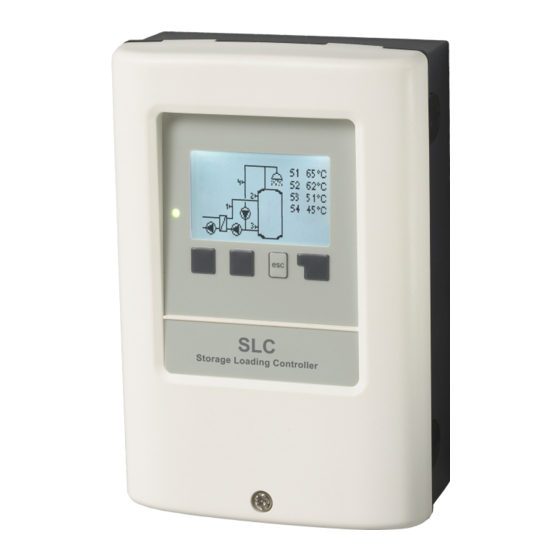
About the Controller The Storage Loading Controller SLC facilitates efficient use and function control of your solar or heating system possible while its hand- ling is intuitive. After every input step the suitable functions are matched to the keys and explained in a text above. In the menu 'meas- urement values and settings' are help text and graphics in addition to key words. -
Page 6: Scope Of Supply
Scope of Supply Storage Loading Controller SLC Installation and operating instructions Optionally contained depending on design/order: external switching relay for V1/V2: Art. No. 77502 Hydraulic Variants The following illustrations should be regarded only as schematic representations of the respective hydraulic systems and do not claim to be complete. Under no cir- cumstances should the controller replace any safety devices. -
Page 7: Installation
Installation Electrical Terminals Low voltages Mains voltages max. 12 VAC / DC 100 - 240 VAC, 50 - 60 Hz Terminal: Connection for: Terminal: Connection for: Storage top Network neutral conductor N Storage bottom Network outer conductor L Ciculation temp. (opt.) Additional function For use see hydraulic variants page 12 Additional function... -
Page 8: Wall Installation
Wall Installation 1. Unscrew cover screw completely. 2. Carefully pull upper part of housing from lower part. During the removal, the brackets are released as well. 3. Set upper part of housing aside Do not touch the electronics. 4. Hold the lower part of the housing up to the selec- ted position and mark the three mounting holes. -
Page 9: Temperature Resistance Table For Pt1000 Sensors
Temperature Resistance Table for Pt1000 Sensors °C Ω 1000 1039 1077 1116 1155 1194 1232 1270 1308 1347 1385 Operation Display and Input The display‘s (1), extensive text and graphical mode, enables simple, almost self-explanatory, operation of the controller. The LED (2) lights up green when the primary pump is switched on (automatic mode). -
Page 10: Commissioning Help
Commissioning help 1. Set language and time 2. Commissioning help / setup wizard a) select or b) skip. The setup wizard guides through the necessary basic settings in the correct order. Jeder Parameter wird im Regler- display. Pressing the „esc“ key takes you back to the previous setting. b) With free commissioning the settings should be made in the following order: Menu 9. -
Page 11: Statistics
2. Statistics Serve for function control and long-term monitoring of the system. For time-dependent functions such as circulation and anti-legionella and the evaluation of system data, it is essential that the time is accur- ately set on the controller. Please note that the clock continues to run for about 24 hours if the mains voltage is interrupted, and afterward must be reset. -
Page 12: Operating Mode
3. Operating mode Auto The automatic mode is the normal mode of the controller. A correct controller function under consideration of the current temperatures and the set parameters is only present in automatic mode! After an interruption of the mains voltage, the controller automatically returns to the last operating mode selected. -
Page 13: Settings
4. Settings By no means does the controller replace the safety appliances on site! Minimum storage temperature If this value falls below this value at the associated storage sensor outside the enable times for heating, the heating is nevertheless star- ted. -
Page 14: Seizing Protection
In the delivery state, the anti legionella function is switched off. As soon as it has heated up with “AL” turned on, information with the date will be shown in the display. This anti legionella function does not offer any secure protection against legionella, because the controller requires an adequate added amount of energy and the temperatures cannot be monitored in the entire storage area and the connected pipe system. -
Page 15: Type Of Pump/ Type Of Signal
Type of pump/ Type of signal The type of speed controlled pump used can be set here. 0-10V: Control of special pumps (e.g. high efficiency pumps) through a 0-10V signal. PWM: Control of special pumps (e.g. high efficiency pumps) through a PWM signal. Pump/ Profile In this menu, the preset profiles for the pump can be selected or under “manual”... -
Page 16: Circulation
The sequence in this list does not correspond to the menu numbering in the controller. Circulation Depending on the temperature and time approval, a circulation pump is turned on for the DHW storage. Circulation Activate function. Tmin If this value at the circulation sensor is undershot and the circulation is approved or there is a request through a tapping process, the circulation pump is started. -
Page 17: Primary Mixer
Primary Mixer When this function is activated, water is mixed in the primary circuit by a mixer via the primary return. As a result, less energy is drawn from the storage tank at high storage tank temperatures, depending on the flow rate, since energy is mixed from the return flow. Primary flow temp. -
Page 18: Pressure Monitor
Please pay attention to the technical information for the PWM/0-10V outputs. Pressure monitor In this menu, the system pressure monitoring can be activated through a direct sensor. As soon as the set pressure conditions are undershot or exceeded, the set relay will switch on. Pressure monitor Relay turns on if the pressure goes below the minimum or exceeds the maximum. -
Page 19: Eco Display Mode
You can find the address of the connector or respectively the data logger on the address sticker on the outside of the casing. Pointers and help on how to establish a connection you can find in the enclosed SOREL Connect instructions or the instructions of the data log- ger. -
Page 20: Menu Lock
7. Menu Lock Secure the controller against unintentional changing and compromise of basic functions. Menu lock active = "On" Menu lock off = "Off" In addition, the "Simple" menu view can be used to hide menu items that are not necessary for the daily use of the controller after commissioning. -
Page 21: Malfunctions/Maintenance
Malfunctions/Maintenance Replacing the Fuse Repairs and maintenance may only be performed by a specialist. Before working on the unit, switch off the power supply and secure it against being switched on again! Check that there is no power flowing! Only use the included safeguard or a similar safeguard with the following specifications: T2A / 250 V. - Page 22 Tips The service values include not only current measurement values and operating states, but also all of the settings for the con- troller. Write the service values down just once after commissioning has been successfully completed. In the event of uncertainty as to the control response or malfunctions the service values are a proven and successful method for remote diagnosis.
- Page 23 Subject as a basic principle to errors and technical changes. Date and time of installation: Name of installation company: Space for notes: Your specialist dealer: Manufacturer: SOREL GmbH microelettronica Reme-Str. 12 D - 58300 Wetter (Ruhr) +49 (0)2335 682 77 0 +49 (0)2335 682 77 10 info@sorel.de www.sorel.de...
Need help?
Do you have a question about the SLC and is the answer not in the manual?
Questions and answers