
Related Manuals for Sorel MHCC


Summary of Contents for Sorel MHCC
- Page 1 Heating Controller MHCC Weather-compensated heating circuit controller Installation and operating instructions Read carefully before installation, commissioning and operation...
-
Page 2: Table Of Contents
Pause Factor Changes to the Unit Increase Warranty and Liability Room Controller heating circ. (X) Disposal and Pollutants Eco Display Mode Network Description MHCC Access Control About the Controller Ethernet Scope of supply CAN bus ID Specifications Hydraulic Variants 8. Menu Lock Installation 9. -
Page 3: Safety Instructions
Safety Instructions EU-Conformity By affixing the CE mark to the unit the manufacturer declares that the MHCC conforms to the following relevant safety regulations: EU low voltage directive 2014/35/EU EU electromagnetic compatibility directive 2014/30/EU conforms. Conformity has been verified and the corresponding documentation and the EU declaration of conformity are kept on file by the manufacturer. -
Page 4: Changes To The Unit
Changes to the Unit Changes, additions to or conversion of the unit are not permitted without written permission from the man- ufacturer. It is likewise forbidden to install additional components that have not been tested together with the unit. If it becomes clear that safe operation of the unit is no longer possible, for example because of damage to the housing, turn the Unit off immediately. -
Page 5: Description Mhcc
In the menu 'measurement values and settings' are help text and graphics in addition to key words. The MHCC can be used with different variants of installations, see " Hydraulic Variants " on page 7. Important characteristics of the MHCC are: Depiction of graphics and texts using a lit display. -
Page 6: Specifications
Specifications Model MHCC Weather-compensated heating circuit controller Temperature controller class Energy efficiency Class VIII / 5% with 3 °CALEON possible Standby loss Request type heater Electrical specifications: Power supply 230 VAC +/- 10%, 50 ... 60 Hz Power consumption / standby... -
Page 7: Hydraulic Variants
Hydraulic Variants The following illustrations should be regarded only as schematic representations of the respective hydraulic systems and do not claim to be complete. Under no circumstances should the controller replace any safety devices. Depend- ing on the specific application, additional system and safety components such as check valves, non-return valves, safety temperature limiters, scalding protectors, etc., may be required. -
Page 8: Installation
Installation Electrical Terminals Low voltages Mains voltages max. 24 VAC / DC 230 VAC 50 - 60 Hz Terminal: Connection for: Terminal: Connection for: Outdoor sensor Pump Outdoor sensor (GND) Pump Flow temperature sensor Mains phase conductor Flow temperature sensor (GND) Mains phase conductor Room sensor (RC21) Neutral Mixer... -
Page 9: Rc21 Remote Adjuster With Thermostat
RC21 Remote adjuster with thermostat The RC21 is an optional accessory and is normally not included in the scope of supply. The remote adjuster with integrated thermostat RC21 provides you with easy to use temperature controlled adjustment of heating from within your living space. Settings The dial is used to parallel translate the heating curve. -
Page 10: Wall Installation
Wall Installation 1. Unscrew cover screw completely. 2. Carefully pull upper part of housing from lower part. During the removal, the brackets are released as well. 3. Set upper part of housing aside Do not touch the electronics. 4. Hold the lower part of the housing up to the selected position and mark the three mounting holes. -
Page 11: Installing The Temperature Sensors
Installing the Temperature Sensors The controller operates with Pt1000 temperature sensors which are accurate to 1 °C, ensuring optimal control of system func- tions. If desired, the sensor cables can be extended to a maximum of 30 m using a cable with a cross-section of at least 0.75 mm². -
Page 12: Operation
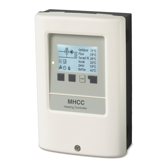
Operation Display and Input The display‘s (1), extensive text and graphical mode, enables simple, almost self-explanatory, operation of the con- troller. The LED (2) lights up green when a relay is switched on. The LED (2) lights up red when operating mode ‚Off‘ is set. The LED (2) flashes quickly red when an error is present. -
Page 13: Commissioning Help
Commissioning help 1. Set language and time 2. Commissioning help / setup wizard a) select or b) skip. The setup wizard guides through the necessary basic settings in the cor- rect order. Each parameter is explained in the control display. Pressing the „esc“ key takes you back to the previous setting. b) With free commissioning the settings should be made in the following order: menu 10. -
Page 14: Today
Today Flow temperature of the last 24 hours In the graphical overview the characteristics of outdoor and flow temperature for the present day is shown from 0 ... 24 h. The right button changes the unit of time (days) and the two left buttons scroll through the diagram. 28 days Flow temperature during the last 28 days In the graphical overview the characteristics of the outdoor and flow temperature during the last 28 days is shown. -
Page 15: Operating Mode
4. Operating mode To specify the operating modes for the heating circuit. After an interruption of the mains voltage, the controller automatically returns to the last operating mode selected. Only in automatic mode does the controller use the set operating times and the correspondingly set target flow temperatures! Manual In ‚Manual‘... -
Page 16: Day Correction
The characteristic curve is used to control the heat dissipation of the heating circuit relative to the outdoor temperature. The demand for heat differs due to factors such as the type of building, heating, insulation and outdoor temperature. For this reason, the controller can operate with a normal straight curve (setting ‚simple‘) or split curve (setting ‚split‘). -
Page 17: Turn Off Hc
Example: Calculated target VL heating circuit 43 ° C, measured VL at sensor S2 40 ° C. If the VL sensor exceeds the setpoint VL by 2K (preferece/actual -) for more than 2 minutes, the MHCC requests a heat source with 4.3V (corresponds to 43 °... -
Page 18: Protective Functions
6. Protective Functions The 'Protective functions‘ can be used by specialists to activate and set vari- ous protective functions. By no means does the controller replace the safety appliances on site! Seizing Protection If the anti-seizing protection is activated, the controller switches the heat pump and the mixer on/off at 12:00 noon for 5 seconds to prevent seizing of the pump/valve after long periods of inactivity. -
Page 19: Special Functions
7. Special Functions Used to set basic items and expanded functions. The settings in this menu should only be changed by a specialist. Sensor Calibration Deviations in the temperature values displayed, for example. due to cables which are too long or sensors which are not posi- tioned optimally can be compensated for manually here. -
Page 20: Eco Display Mode
You can find the address of the connector or respectively the data logger on the address sticker on the outside of the casing. Pointers and help on how to establish a connection you can find in the enclosed SOREL connect instructions or the instructions of the data logger. -
Page 21: Can Bus Id
Gateway Please refer to the router configuration for the gateway to be set. DNS-Server Please refer to the router configuration for the DNS server to be set. CAN bus ID Here you can see the ID of the controller on the CAN bus. 8. -
Page 22: Malfunctions/Maintenance
Malfunctions/Maintenance Replacing the Fuse Repairs and maintenance may only be performed by a specialist. Before working on the unit, switch off the power sup- ply and secure it against being switched on again! Check that there is no power flowing! Only use the supplied spare fuse or a fuse of the same design with the following specifications: 2 AT/250 VSOREL Art. -
Page 23: Additional Information
Additional Information External relay at signal output V(X) (0-10V / PWM) In order to use a 0-10V / PWM output as a 230V / AC switching output, an external switching relay (Art. No. 77502) can be connect at the output V (X) (V1, V2, ...). - Page 24 Subject as a basic principle to errors and technical changes. Date and time of installation: Name of installation company: Space for notes: Your specialist dealer: Manufacturer: SOREL GmbH Mikroelektronik Reme-Str. 12 D - 58300 Wetter (Ruhr) +49 (0)2335 682 77 0 +49 (0)2335 682 77 10 info@sorel.de www.sorel.de...
Need help?
Do you have a question about the MHCC and is the answer not in the manual?
Questions and answers