Sorel MTDC Installation And Operating Instructions Manual
Temperature difference controller
Hide thumbs
Also See for MTDC:
- Installation and operating instructions manual (48 pages) ,
- Installation and operating instructions manual (32 pages)

Related Manuals for Sorel MTDC


Summary of Contents for Sorel MTDC
- Page 1 Temperature difference controller MTDC Installation and operating instructions Read carefully before installation, commissioning and operation...
-
Page 2: Table Of Contents
Explanation of Symbols Relay functions Changes to the Unit Solar bypass Warranty and Liability Solar bypass Disposal and Pollutants Variant Bypass sensor Description MTDC Thermostat About the Controller DHW request Specifications Heating Circuit request Scope of Supply Tset Hydraulic Variants... - Page 3 Delay Follow-up time Always on Heating circuit Heating circuit Room Reference (Day) Room Reference (Night) Room Periods Heat quantity Flow temperature sensor (X) Return flow sensor Glycol type Glycol percentage Flow rate supply flow (X) Offset ∆T Sensor Calibration Commissioning Factory Settings Starting aid Purging time...
-
Page 4: Safety Instructions
Safety Instructions EU-Conformity By affixing the CE mark to the unit the manufacturer declares that theMTDC conforms to the following relevant safety regulations: EU low voltage directive 2014/35/EU EU electromagnetic compatibility directive 2014/30/EU conforms. Conformity has been verified and the corresponding documentation and the EU declaration of conformity are kept on file by the manufacturer. -
Page 5: Changes To The Unit
About the Controller The Temperature difference controller MTDC facilitates efficient use and function control of your solar or heating system possible while its handling is intuitive. After every input step the suitable functions are matched to the keys and explained in a text above. In the menu 'measurement values and settings' are help text and graphics in addition to key words. -
Page 6: Specifications
Scope of Supply Temperature difference controllerMTDC 3 screws 3,5 x 35 mm and 3 plugs 6 mm for wall installation. MTDC Installation and operating instructions Optionally contained depending on design/order: CAN Bus Accessories: Datalogger with Ethernet connection External relay for V1: 77502... -
Page 7: Hydraulic Variants
Hydraulic Variants The following illustrations should be regarded only as schematic representations of the respective hydraulic systems and do not claim to be complete. Under no cir- cumstances should the controller replace any safety devices. Depending on the specific application, additional system and safety components such as check valves, non-return valves, safety temperature limiters, scalding protectors, etc., may be required. - Page 8 Solar with 2 collector surfaces and 2 Solar with 2 storages and switching Solar with 2 storages and 2 pumps pumps valve Solar with storage transfer Solar with pool and heat exchanger Solar with thermostat and switching valve Solar and solid-fuel boiler Solar with cooling 1 (collector cooling) Solar with cooling 2 (collector cooling) Solar with cooling 3 (collector cool-...
-
Page 9: Installation
Installation Electrical Terminals Low voltages Mains voltages max. 12 VAC / DC 230 VAC 50 - 60 Hz On the control board CAN bus connection 1= high 2= low CAN bus connection 1= high 2= low Terminal: Connection for: Terminal: Connection for: Temperature Sensor 1 Neutral conductor R1... -
Page 10: Wall Installation
4. Clip on the terminal cover again and close it with the screw. 5. Turn on mains supply and put the controller into oper- ation. If problems occur with the operation of the terminals, our video on our YouTube page can help you: http://www.sorel.de/youtube... -
Page 11: Electrical Connection
Electrical Connection Before working on the unit, switch off the power supply and secure it against being switched on again! Check that there is no power flowing! Electrical connections may only be made by a specialist and in compliance with the applicable reg- ulations. -
Page 12: Operation
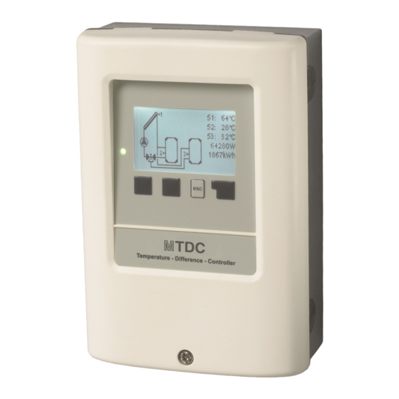
Operation Display and Input The display‘s (1), extensive text and graphical mode, enables simple, almost self-explanatory, operation of the controller. The LED (2) lights up green when the primary pump is switched on (automatic mode). The LED (2) lights up red when operating mode ‚Off‘... -
Page 13: Commissioning Help
Commissioning help 1. Set language and time 2. Commissioning help / setup wizard a) select or b) skip. The setup wizard guides through the necessary basic settings in the correct order. Every parameter is explained on the display of the controller. Pressing the „esc“... -
Page 14: Statistics
2. Statistics Serve for function control and long-term monitoring of the system. For time-dependent functions such as circulation and anti-legionella and the evaluation of system data, it is essential that the time is accur- ately set on the controller. Please note that the clock continues to run for about 24 hours if the mains voltage is interrupted, and afterward must be reset. -
Page 15: Operating Mode
3. Operating mode Auto The automatic mode is the normal mode of the controller. A correct controller function under consideration of the current temperatures and the set parameters is only present in automatic mode! After an interruption of the mains voltage, the controller automatically returns to the last operating mode selected. -
Page 16: Settings
4. Settings By no means does the controller replace the safety appliances on site! Tmin S1 Enable/start temperature at sensor 1: If this value on the sensor 1 (collector sensor) is exceeded and the other conditions are not fulfilled, the controller will turn on the affil- iated pump or the valve. -
Page 17: Tmax Pool / Tmax Pool He
The priority for the first storage is thus set under priority S2 and for the 2. storage under priority S3. Tmax Pool / Tmax Pool HE Switch-off temperature at heat exchanger sensor. If this value is exceeded at the specified sensor, the controller turn off the affiliated pump or the valve. -
Page 18: Recooling
Recooling In the system hydraulics with solar, excess energy is guided from the storage back to the collector with an activated return cooling func- tion. This only occurs if the temperature in the storage is greater than the value “Return cooling Tref” and the collector is at least 20 °C colder than the storage and until the storage temperature has fallen below the value “Return cooling Tref”. -
Page 19: Signal Type
Signal type Only available, if the function is used on one of the V-outputs. The type of device to be controlled is set here. 0-10V: Control by 0-10V signal. PWM: Control by means of a PWM signal. Output Signal In this menu the type of actors are set: heating pumps have the greatest output with a small input signal, solar pumps in contrast have very little output with a small input signal. -
Page 20: Min. Speed
The specified percentages are variables, which may deviate more or less strongly depending on the system, pump and pump level. 100% is the maximum possible power of the controller. Min. Speed The minimum speed of the pump is determined here. During the setting, the pump runs in the respective speed and the flow can be determined. -
Page 21: Dhw Request
Other values, for example, Teco, apply in economy mode. Thermostat DHW request Thermostat is started for a DHW - heat request. Heating Circuit request Thermostat is started with a heating circuit - heat request. Tset The target temperature of the thermostat sensor 1. Below this temperature, the thermostat turns on until Tset+ Hysteresis is reached. Hysteresis Hysteresis of set point temperature. -
Page 22: Hysteresis
Hysteresis When the temperature at the cooling sensor Tset + Hys, the relay is switched off. Cooling sensor Reference sensor of the cooling function. Periods Cooling release times Here the desired periods are set in which the cooling function is approved. For each weekday, three times can be specified, furthermore, you can copy individual day to other days. -
Page 23: Heat Transfer
With the help of the anti legionella function (hereinafter referred to as: AL), the system can be heated up at selected times in order to free it of legionella. In the delivery state, the anti legionella function is switched off. Antilegionella function is not shown in the menu “Protective functions”. -
Page 24: Difference
Difference The assigned relay is activated as soon as there is a preset temperature difference (ΔT on/off) between the source and target sensors. Difference Tmin Source Minimum temperature on the source sensor for approval of the difference relay. If the temperature on the source sensor is below this value, the difference function will not be switched on. Δ... -
Page 25: Solid Fuel Boiler
Solid fuel boiler In solid-fuel boiler function, a pump is controlled with a assigned relay, which loads the heat energy from a solid-fuel boiler into a stor- age tank. The solid-fuel boiler function controls the charge pump of a solid-fuel boiler based on the temperature difference between the solid- fuel boiler sensor and the storage tank sensor. -
Page 26: Error Messages
Error Messages The relay is switched on if one or several of the set protective functions are activated. This function can be inverted so that the relay is turned on (Duration on) and then turned off again if a protective function is activated. Pressure monitor In this menu, the system pressure monitoring can be activated through a direct sensor. -
Page 27: Heating Circuit
Heating circuit In the heating function, a simple heating circuit in the system controls the time and temperature. The settings of the heating circuit define "Room Reference (Day)" and "Room Reference (Night)” values for the associated room sensor. Heating circuit Activate function. -
Page 28: Sensor Calibration
Sensor Calibration Deviations in the temperature values displayed, for example. due to cables which are too long or sensors which are not positioned optimally can be compensated for manually here. The settings can be made for each individual sensor in steps of 0.5 °C. Settings are only necessary in special cases at the time of initial commissioning by the specialist. -
Page 29: Temperature Unit
You can find the address of the connector or respectively the data logger on the address sticker on the outside of the casing. Pointers and help on how to establish a connection you can find in the enclosed SOREL Connect instructions or the instructions of the data log- ger. -
Page 30: Menu Lock
7. Menu Lock Secure the controller against unintentional changing and compromise of basic func- tions. Menu lock active = "On" Menu lock off = "Off" In addition, the "Simple" menu view can be used to hide menu items that are not necessary for the daily use of the controller after commissioning. -
Page 31: Malfunctions/Maintenance
Malfunctions/Maintenance Replacing the Fuse Repairs and maintenance may only be performed by a specialist. Before working on the unit, switch off the power supply and secure it against being switched on again! Check that there is no power flowing! Only use the included safeguard or a similar safeguard with the following specifications: T2A / 250 V. -
Page 32: Additional Information
Additional Information CAN bus 1. The CAN devices are connected in series with the CAN bus cable. 2. The first and last CAN device in this connection in series must be fitted with terminating resistance. The wiring of the two CAN sockets is arbitrary. Tips The service values include not only current measurement values and operating states, but also all of the settings for the con- troller. -
Page 33: Final Declaration
Date and time of installation: Name of installation company: Space for notes: Your specialist dealer: Manufacturer: SOREL GmbH Mikroelektronik Reme-Str. 12 D - 58300 Wetter (Ruhr) +49 (0)2335 682 77 0 +49 (0)2335 682 77 10 info@sorel.de www.sorel.de...
Need help?
Do you have a question about the MTDC and is the answer not in the manual?
Questions and answers
Red light flashing and fault reported as sencor faulty but renewed and still have problem
If your Sorel MTDC has a red light flashing and reports a sensor fault even after renewal, follow these steps:
1. Check if the warning symbol changes to an info symbol, indicating the error is no longer present.
2. Press the key under the warning or info symbol to get more detailed information on the error.
3. The fault may be due to a defective sensor, a faulty sensor input at the controller, or a damaged connecting cable.
4. Do not attempt to fix it yourself. Consult a specialist for further diagnosis and repair.
This answer is automatically generated