
Related Manuals for Sorel HCC 4


Summary of Contents for Sorel HCC 4
- Page 1 Heating-Controller HCC 4 Weathercontrolled heat circuit regulator Installation and operating instructions Read carefully before installation, commissioning and operation...
-
Page 2: Table Of Contents
Content page page EC declaration of conformity Settings Heating circuit General instructions Su/Wi Day Explanation of symbols Su/Wi Night Changes to the unit Curve Warranty and liability Day correction Night correction Specifications Comfort temperature boost Temperature resistance table Reference/actual - for Pt1000 sensors Reference/actual + About the controller... -
Page 3: Ec Declaration Of Conformity
Safety instructions EC declaration of conformity By affixing the CE mark to the unit the manufacturer declares that the HCC4 conforms to the following relevant safety regulations: EC low voltage directive 73/23/EEC, as amended by 93/68/EEC EC electromagnetic compatibility directive 89/336/EEC version 92/31/EEC version 93/68/EEC Conformity has been verified and the corresponding documentation and the EC declaration of conformity are kept on file by the manufacturer. General instructions It is essential that you read this! These installation and operating instructions contain basic instructions and important information regarding safety, installation, commissioning, maintenance and the optimal use of the unit. -
Page 4: Changes To The Unit
Safety instructions Changes to the unit Changes to the unit can compromise the safety and function of theunit or the entire system. Danger Changes, additions to or conversion of the unit are not permitted without written permission from the manufacturer It is likewise forbidden to install additional components that have not been tested together with the unit If it becomes clear that safe operation of the unit is no longer possible, for example because of damage to the housing, then turn the controller off immediately Any parts of the unit or accessories that are not in perfect condition must... -
Page 5: Specifications
Description of controller Specifications Electrical specifications: Mains Voltage 230VAC +/- 10% Mains frequency 50...60Hz Power consumption Total switched power 460VA (Relay outputs 1-5) Switched power per relay 460VA for AC1 / 185W for AC3 Internal fuse 2A slow blow 250V Protection category IP40 Protection class Sensor inputs 5x Pt1000 temperature sensor 1x Room Measuring range -40 to110°C Permissible ambient conditions: Ambient temperature for controller operation 0°C...40°C... -
Page 6: About The Controller
Description of controller About the controller The weather controlled Heat Circuit Controller HCC 4 facilitates efficient use and func- tion control of your heating system. The device is impressive most of all for its functionality and simple, almost self-explanatory operation. For each step in the input process the individual entry keys are assigned to appropriate functions and explained. The controller menu contains headwords for the measured values and settings, as well as help texts or clearly-structured graphics. Important characteristics of the HCC4: •... -
Page 7: Hydraulic Variants
Description of controller Hydraulic variants The following illustrations should be viewed only as schematic diagrams showing the respective hydraulic systems, and do not claim to be comple- te. The controller does not replace safety devices under any circumstan- ces. Depending on the specific application, additional system compo- nents and safety components may be mandatory, such as check valves, Caution non-return valves, safety temperature limiters, scalding protectors, etc., and must therefore be provided. Regulated heating circuit Regulated heating circuit without add. heating... -
Page 8: Wall Installation
Installation Wall installation Install the controller only in dry areas and under the ambient conditions described under B.1 „Specifications“. Carry out the following steps 1-8. Caution 1. Unscrew cover screw completely C.1.1 2. Carefully pull upper part of housing from lower part. 3. Set upper part of housing aside, being sure not to touch the electronics when doing so. -
Page 9: Electrical Connection
Installation Electrical connection Before working on the unit, switch off the power supply and secure it against being switched on again! Check for the absence of power! Electrical connections may only be made by a specialist and in comp- Danger liance with the applicable regulations. The controller may not be put into operation if there is visible damage to the housing, e.g. cracks. Low-voltage cables such as temperature sensor cables must be routed separately from mains voltage cables. Feed temperature sensor cables only into the left-hand side of the unit, and mains voltage cables only into Caution the right-hand side. -
Page 10: Installing The Temperature Sensors
Installation Installing the temperature sensors Der Regler arbeitet mit Pt1000-Temperaturfühlern, die für eine gradgenaue Tempera- turerfassung sorgen, um die Anlagenfunktion regeltechnisch optimal sicherzustellen. If desired the sensor cables can be extended to a maximum of 30m using a cable with a cross-section of at least 0.75mm². Make sure that there is no contact resistance! Position the sensor precisely in the area to be measured! Caution Only use immersion, pipe-mounted or fl at-mounted sensor suitable for the spe- cific area of application with the appropriate permissible temperature range. -
Page 11: D Electrical Terminals
Installation Electrical terminals Left-hand terminal Right-hand terminal compartment only for compartment only for mains Caution Danger low voltage if voltages of max. 12VAC/DC 230VAC 50-60Hz Connections low voltage: Connections Mains Voltage: - Temperature sensors S1 - S6 - Protective conductor PE metal terminal (polarity freely selectable) block - Optional additional functions Z1/Z2 - Neutral conductor terminal block N - Mains phase conductor L - Switch output R1-R4... -
Page 12: Display And Input
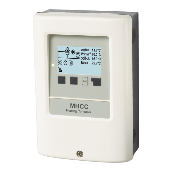
Operation Display and input The display (1), with its extensive text and graphics mode, is almost self-explanatory, allowing easy operation of the controller. The LED (2) lights up green when a relay is switched on. The LED (2) lights up red when operating mode „Off“ is set. The LED (2) fl ashes slowly red in the ope- rating mode „Manual“. The LED (2) flashes quickly red when an error is present. Entries are made using four keys (3+4), to Examples of display symbols: which different functions are assigned de- Examples of display symbols: pending on the situation. The „esc“ key (3) is used to cancel an entry or to exit a menu. -
Page 13: Commissioning Help
Operation Commissioning help The first time the controller is turned on and after the language and time are set, a query appears as to whether you want to parametrise the controller using the com- missioning help or not. The commissioning help can also be terminated or called up again at any time in the special functions menu. -
Page 14: Menu Sequence And Menu Structure
Operation Menu sequence and menu structure The graphics or overview mode appears when no key has been pressed for 2 mi- nutes, or when the main menu is exited by pressing „esc“. Pressing a key in graphics or overview mode takes you directly to the main menu. The following menu items are then availab- le for selection there: Current temperature values with Measurements explanations Function control of the system with Statistics operating hours, etc. Operating times for heating circuit and hot Times water, setting the clock... -
Page 15: Measurement Values
Measurement values Measurement values Menu “1. Measurement values” serves to display the currently measured tempera- tures. The menu is closed by pressing “esc” or selecting “Exit measurement values”. Selecting “Info” leads to a brief help text explaining the measurement values. Selecting “Overview” or “esc” exits the Info mode. If “Error” appears on the display instead of the measurement value, then there may be a defective or incorrect temperature sensor. -
Page 16: Statistics
Statistics Statistics Menu “2. Statistics” is used for function control and long-term monitoring of the system. The menu is closed by pressing “esc” or selecting “Exit statistics”. For system data statistics it is essential for the time to be set accurately on the controller. Please note that the clock continues to run for about 24 hours if the mains voltage is interrupted, and after that has to be reset. -
Page 17: Times
Times Times Menu “3. Times” is used to set the time, date, operating times for the heating circuit and hot water. The associated temperature re- ference values are specified in menu 5 “Settings”! Caution The menu is closed by pressing “esc” or selecting “Exit display mode”. 3.1 Time & Date This menu is used to set the current time and date. -
Page 18: Operating Modes
Operating modes Operating modes Menu “4. Operating modes” is used to spe- cify the operating modes for the heating circuit. After an interruption of the mains voltage the controller automatically returns to the last operating mode selected! The menu is closed by pressing “esc” or selecting “Exit operating modes”. The controller works with the set operating times and the corresponding different reference flow temperature values only in the automatic mode. -
Page 19: Manual
Operating modes 4.3 Manual In Manual mode the individual relay outputs and the connected consumers can be che- cked for proper functioning and correct assignment. Function in manual mode: The relays and thus the connected consumer are switched on and off by pressing a key, with no regard to the current temperatures and the parameters which have been set. At the same time, the current measurement values of temperature sensors are also shown in the display for the purposes of function control. The operating mode “Manual” may only be used by specialists for brief function tests, e.g. -
Page 20: Settings Heating Circuit
Settings Heating circuit Settings Heating circuit The necessary basic settings required for the control function of the heating circuit are made in menu “5. Settings HC”. This does not under any circum- stances replace the safety facilities to be provided by the customer! Caution The menu is closed by pressing “esc” or selecting “Exit settings”. -
Page 21: Curve
Settings Heating circuit 5.3 Curve Slope of the characteristic heating curve The characteristic curve is used to control the heat dissipation of the heating circuit re- lative to the outdoor temperature. The demand for heat is different due to differences in the type of building/insulation/type of heating/outdoor temperature. For this reason the controller can make use of a normal straight curve (Setting simple) or a split curve (Setting split). In the simple setting the curve can be adjusted with the help of the graphic diagram. The slope is changed, and the calculated reference flow temperature is displayed for -12 °C. If the split mode is selected, the characteristic curve is adjusted in 3 steps. First the stan- dard slope has to be set, after that the split point and finally the steepness of the curve after the split. -
Page 22: Day Correction
Settings Heating circuit The following settings can be used for parallel translation of the characte- ristic for certain time periods such as daytime and nighttime mode. Caution 5.4 Day correction Parallel translation of the characteristic curve The day correction produces a parallel translation of the heating characteristic during the daytime operating hours, since depending on the outdoor temperature it is possible that the building may not be optimally heated with the set characteristic. If the charac- teristic is not optimised, the following situation may occur: in hot weather - the spaces are too cold in cold weather - the spaces are too hot In this case, one should gradually... -
Page 23: Reference/Actual
Settings Heating circuit 5.7 Reference/actual - Switch on hysteresis for additional heating This setting determines the allowed undershoot of the heat circuit temperature under the calculated reference flow temperature. If the heat circuit flow temperature falls below the reference temperature by this value, the additional heating (R5) is activated after a delay of 5 minutes. Settings range: -10°C to 10°C / Default: -2°C The additional heating (relais R5) is started when the flow temperature (in case of 2 heat circuits: one of the flow temperatures)is below the refe- rence flow temperature for 5 minutes continously. Caution 5.8 Reference/actual + Switch off hysteresis (only if S4 is connected) This settings determines the allowed overstepping of the heat circuit temperature to the calculated reference flow temperature at sensor 4. If the temperature at S4 exceeds the reference flow temperature by this value, the additional heating (R5) is switched off. -
Page 24: Curve
Settings Heating circuit 2 Settings Heating circuit 2 The necessary basic settings required for the control function of the 2nd heating cir- cuit are made in menu “6. Settings HC 2”. The menu is closed by pressing “esc” or selecting “Exit settings”. This does not under any circum- stances replace the safety facilities to be provided by the customer! Caution The settings for Su/Wi Day, Su/Wi Night, Reference/actual- and Refe- rence/actual+, which are made in “Settings heat circuit” are applied to... -
Page 25: Day Correction
Settings Heating circuit 2 The following settings can be used for parallel translation of the characte- ristic for certain time periods such as daytime and nighttime mode. Caution 6.2 Day correction Parallel translation of the characteristic The day correction produces a parallel translation of the heating characteristic during the daytime operating hours, since depending on the outdoor temperature it is possible that the building may not be optimally heated with the set characteristic. If the characte- ristic is not optimised, the following situation may occur: in hot weather - the spaces are too cold... -
Page 26: Protective Functions
Protective functions Protective functions Menu “7. Protective functions” can be used by specialists to activate and set various protective functions. The menu is closed by pressing “esc” or selecting “Exit settings”. This does not under any circum- stances replace the safety facilities to be provided by the customer! Caution 7.1 Anti-seizing protection If the anti-seizing protection is activated, the controller switches the heat pump and the mixer on/off at 12:00 pm for 5 seconds to prevent seizing of the pump/valve after long periods of inactivation. -
Page 27: Max. Flow
Protective functions 7.4 max. flow This is used as the upper limit for the reference flow temperature of the heat circuit. Should the heat circuit temperature exceed this value, the heat circuit is switched off until the temperature drops below. Settings range: 30 °C to 105 °C / Default: 45 °C For safety, the customer must provide an additional limiting thermostat- which is connected to the pumps in series. -
Page 28: Special Functions
Special functions Special functions Menu “8. Special functions” is used to set basic items and expanded functions. The menu is closed by pressing “esc” or selecting “Exit special functions”. The settings in this menu should only be made by a specialist. Caution 8.1 Sensor calibration Deviations in the temperature values displayed, for example due to cables which are to long or sensors which are not positioned optimally, can be compensated for manually here. The settings can be made for each individual sensor in steps of 0.5°C. Offset S1...S6 per settings range : -10°C...+10°C Default : 0°C Settings are only necessary in special cases at the time of initial com- missioning by the specialist. -
Page 29: Expansions
Special functions 8.4 Expansions This menu can only be selected and used if additional options or expansion modules have been built into the controller. The associated supplementary installation, mounting and operation instructions are then included with the specific expansion. 8.5 Mixer 8.5.1 Turn time The mixer is switched on i.e. is opening or closing for the timespan set here, then the temperature is measured to control the flow temperature. Settings range: 0.5 sec to 3 sec. / Default: 2 sec. 8.5.2 Pause-Factor The calculated pause time of the mixer is multiplied with the value set here. If the pause factor is “1”, the normal pause time is used, “0.5” will use half the normal pause time, “4”... -
Page 30: Room Controller
Special functions 8.6 Room controller The settings necessary for the optional room controller RC21 are made in this menu. The 3 modes “continous day”, “continous night” and “Time controlled/automatic” can be switched at the RC21. Additionally the reference temperature of the flow can be parallel translated by turning the control wheel. If the wheel is set to minimum, only the minum values that can be set in the protective functions menu will be used. 8.6.1 Room controller This value is used to appoint the amount of influence in percent the room temperature has on the reference flow temperature. For every degree of deviation of the room temperature from the reference room temperature the percentage of the calculated reference flow temperature set here is added to or, respectively, subtracted from the reference flow temperature. As long as it is within the limits of the min. and max. flow temperatures that can be set in the protective functions. -
Page 31: Menu Lock
Menu lock Menu lock Menu “9. Menu lock” can be used to secure the controller against unintentional changing and compromise of basic functions. The menu is closed by pressing “esc” or selecting “Exit menu lock”. The menus listed below remain completely accessible despite the menu lock being ac- tivated, and can be used to make adjustments if necessary: 1. Measurement values 2. Statistics 3. Times 8. Menu lock 9. Service values To block the other menus, select “Menu lock on”. To enable the menus again, select “Menu lock off”. Setting range: on, off / default setting: off Language Language Menu “11. Language” can be used to select... -
Page 32: Service Values
Service values Service values Menu “10. Service values” can be used for remote diagnosis by a specialist or the ma- nufacturer in the event of an error, etc. Enter the values at the time when the error occurs into the table. Caution The menu can be closed at any time by pressing “esc”. -
Page 33: Malfunctions With Error Messages
Malfunctions Z.1. Malfunctions with error messages If the controller detects a malfunction, the red light fl ashes and the warning symbol also appears in the display. If the error is no longer present, the warning symbol (Led flashes+ warning symbol) changes to an info symbol and the red light no longer fl ashes. To obtain more detailed information on the error, press the key un- der the warning or info symbol. -
Page 34: Replacing The Fuse
Malfunctions Replacing the fuse Repairs and maintenance may only be performed by a specialist. Before working on the unit, switch off the power supply and secure it against being switched on again! Check for the absence of power! Danger Only use the supplied spare fuse or a fuse of the same design with the following specifications: T2A 250V Danger If the mains voltage is switched on and the Z.2.1 controller still does not function or display Fuse anything, then the internal device fuse may be defective. - Page 35 Useful notes / tips and tricks The service values (see 10.) include not only current measurement values and operating states, but also all of the settings for the controller.Write the service values down just once after commissioning has been successfully completed. In the event of uncertainty as to the control response or malfunctions the ser- vice values are a proven and successful method for remote diagnosis. Write the service values down (see 10.) at the time that the suspected malfunction occurs.
- Page 36 Hydraulic variant set: Commissioned on: Commissioned by: Final declaration: Although these instructions have been created with the greatest possible care, the possibility of incorrect or incomplete information cannot be excluded. Subject as a basic principle to errors and technical changes. Manufacturer: Your specialist dealer: SOREL GmbH Mikroelektronik Reme-Str. 12 D - 58300 Wetter Tel. +49 (0)2335 682 77 0 Fax +49 (0)2335 682 77 10 www.sorel.de info@sorel.de...
Need help?
Do you have a question about the HCC 4 and is the answer not in the manual?
Questions and answers