Table of Contents
Advertisement
Quick Links
Advertisement
Table of Contents

Subscribe to Our Youtube Channel
Related Manuals for Cosmo COS-DFRL486GK


Summary of Contents for Cosmo COS-DFRL486GK
- Page 1 DUAL FUEL RANGE COS-DFRL486GK SLIDE-IN RANGE USER & INSTALLATION MANUAL IMPORTANT: READ AND SAVE THESE INSTRUCTIONS. FOR RESIDENTIAL USE ONLY. INSTALLER: PLEASE LEAVE THESE INSTRUCTIONS WITH THIS UNIT FOR THE OWNER. OWNER: PLEASE RETAIN THESE INSTRUCTIONS FOR FUTURE REFERENCE. Rev.24.04...
- Page 2 COSMO Appliances are designed according to the strictest safety and performance standard for the North American market. We follow the most advanced manufacturing philosophy.
-
Page 3: Table Of Contents
TABLE OF CONTENTS RANGE SAFETY....................6 Anti-tip Device ......................10 Important Safety Instructions ................11 OVERVIEW ......................15 Range Layout ......................15 INSTALLATION INSTRUCTIONS ............... 17 Positioning of Range ....................19 Dimensions and Clearance ................... 19 Top Hood and Cabinet Specifications ..............21 IMPORTANT NOTES TO THE INSTALLER ............ - Page 4 Power Failure ......................37 Cooktop ........................37 Burner Grates ......................38 Oven Burner Use ..................... 38 Broil Burner Use ...................... 39 Oven Cooking Safety Guidelines ................ 40 OVEN FUNCTION ....................41 Natural Airflow Bake ..................... 41 Convection Bake ....................41 Convection Roast ....................
- Page 5 REPLACING BURNER PARTS ................49 REMOVING AND REPLACING OVEN DOOR ............ 50 Removing Oven Door .................... 50 Replacing Oven Door .................... 51 Replacing Oven Light Bulb .................. 52 DUAL BURNER CLICKING PROBLEM ..............53 Step 1 ........................53 Step 2 ........................53 Step 3 ........................
-
Page 6: Range Safety
RANGE SAFETY READ ALL INSTRUCTIONS BEFORE USING THE APPLIANCE Your safety and the safety of others are very important. We have provided many important safety messages in this manual and on your appliance. Always read and obey all safety messages. This is the safety alert symbol. - Page 7 WARNING Electrical Shock Hazard • Before removing a faulty oven light bulb, make sure you turn OFF the power to the range at the main fuse or circuit breaker panel. If you don't know how to do this , contact an electrician. •...
- Page 8 WARNING FIRE AND EXPLOSION HAZARD If the information in this manual is not followed exactly, a fire or explosion may result causing property damage, personal injury or death. • Do not store or use gasoline or other flammable vapors and liquids in the vicinity of this or any other appliance.
- Page 9 WARNING • Gas leaks cannot always be detected by smell. Gas suppliers recommend that you use a gas detector approved by UL or CSA. For more information, contact your gas supplier. • Do not install a ventilation system that blows air downward toward this cooking appliance.
-
Page 10: Anti-Tip Device
ANTI-TIP DEVICE WARNING TIP OVER HAZARD • A child or adult can tip the range and be killed. • Install anti-tip bracket to floor or wall per installation instructions. • Slide range back so rear range foot is engaged in the slot of the floor- mounting anti-tip bracket or rear range pin is engaged under the wall- mounting anti-tip bracket. -
Page 11: Important Safety Instructions
IMPORTANT SAFETY INSTRUCTIONS WARNING: To reduce the risk of fire, electrical shock, injury to persons, or damage when using the range, follow basic precautions, including the following: • WARNING: TO REDUCE THE • CAUTION: Do not store items of RISK OF TIPPING OF THE RANGE, interest to children in cabinets THE RANGE MUST BE SECURED above a range or on the back... - Page 12 IMPORTANT SAFETY INSTRUCTIONS • Do Not Use Water on Grease • Disconnect power before Fires – Smother fire or flame or servicing. use dry chemical or foam-type • Proper Installation – The extinguisher. appliance, when installed, must • Use Only Dry Potholders – Moist be electrically grounded in or damp potholders on hot accordance with local codes, or...
- Page 13 IMPORTANT SAFETY INSTRUCTIONS • Do not use replacement parts • Care must be taken to prevent that have not been aluminum foil and meat probes recommended by the from contacting heating manufacturer (e.g. parts made elements. at home using a 3D printer). •...
- Page 14 IMPORTANT SAFETY INSTRUCTIONS • Proper Disposal of Your For self-cleaning ranges – Appliance – Dispose of or recycle • Before Self-Cleaning the Oven – your appliance in accordance Remove broiler pan and other with Federal and Local utensils. Wipe off all excessive Regulations.
-
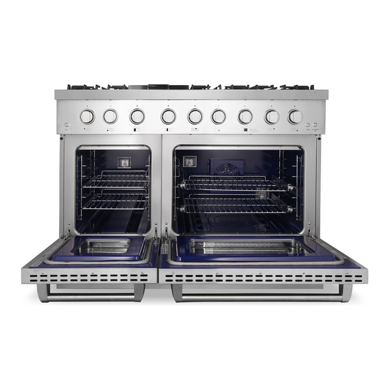
Page 15: Overview
OVERVIEW RANGE LAYOUT The range you have purchased may have some or all of the items listed. The locations and appearances of the features shown here may not match those of your model. - Page 16 • Base Heating Element: 2500W NOTE: • To purchase replacement parts or any other accessories, please visit www.cosmoappliances.com or reference the contact information at the end of this manual. COOKTOP EQUIPMENT Model 2000 BTU 5000 BTU 8000 BTU Griddle 5000 BTU COS-DFRL486GK...
-
Page 17: Installation Instructions
INSTALLATION INSTRUCTIONS WARNING TIP OVER HAZARD • A child or adult can tip the range and be killed. • Install anti-tip bracket to floor or wall per installation instructions. • Slide range back so rear range foot is engaged in the slot of the floor- mounting anti-tip bracket or rear range pin is engaged under the wall- mounting anti-tip bracket. - Page 18 A= 30 inches minimum clearance between the top of the cooking surface and the bottom of an unprotected wood or metal cabinet A= 24 inches minimum when bottom of wood or metal cabinet is protected by not less than 1/4-inch-thick flame-retardant millboard covered with not less than No.
-
Page 19: Positioning Of Range
POSITIONING OF RANGE • You may install a non-combustible material, such as tile, on the rear wall above the range and up the vent hood. • It is not necessary to install non-combustible materials behind the range below the counter top height. •... -
Page 21: Top Hood And Cabinet Specifications
TOP HOOD AND CABINET SPECIFICATIONS Condition Minimum Clearance Allowed Clearance between the top of the cooking 24" surface and the bottom wood or metal cabinet that is protected by not less than: 1/4-inch-thick flame-retardant millboard covered with not less than: •... -
Page 22: Important Notes To The Installer
IMPORTANT NOTES TO THE INSTALLER 1. Read all instructions contained in these installations before installing range. 2. Remove all packing material from the oven compartments before connecting the electrical supply to the range. 3. Anti-tip brackets MUST be installed. 4. Observe all governing codes and ordinances. 5. -
Page 23: Model And Serial Number Location
9. Do not obstruct the flow of combustion air at the oven vent nor around the base or beneath the lower front panel of the range. Avoid touching the vent openings or nearby surfaces as they may become hot while the oven is in operation. -
Page 24: Electrical Installation
This appliance is manufactured ready to be installed with a 4-wire cord set. A 3-Pole, 4-Conductor Cord Kit with NEMA Type 14-50R, 50 Amperes dedicated circuit and marked for use with ranges is recommended by the manufacturer for Cosmo Ranges. 4-wire receptacle (14-50R) Requires a minimum of 50 Amperes with 220 Volts. -
Page 25: Access To Terminal Block
CAUTION Do not loosen the nuts which secure the factory-installed range wiring to terminal block while connecting range. Electrical failure or loss of electrical connection may occur. ACCESS TO TERMINAL BLOCK WARNING • Electrical ground is required on this appliance. •... -
Page 26: Electrical Connection
ELECTRICAL CONNECTION Four Conductor Wire Connection to Range 1. Remove the screws at the lower end of the rear access cover and take it down to expose range terminal connection block. 2. Remove the screws to loosen the cable clamp and pass through the four- conductor wire from the bottom of the range. -
Page 27: Electrical Power Supply Requirements
The wiring diagram for the terminal connection block is on the access cover. The wiring diagram sticker is located here. ELECTRICAL POWER SUPPLY REQUIREMENTS Your range must be electrically grounded in accordance with local codes or in the absence of local codes, in accordance with the National Electrical Code (ANSI/NFPA 70, latest edition). -
Page 29: Electrical Grounding Instructions
ELECTRICAL GROUNDING INSTRUCTIONS WARNING This indoor gas and electric cooking appliance is to be equipped with a 4- 4-prong grounding plug for your protection against shock hazard a should be plugged directly into a properly grounded receptacle. Improper connection of the equipment-grounding conductor can result in a risk of electric shock. -
Page 30: Gas Supply Requirement
GAS SUPPLY REQUIREMENT Installation of this range must conform with local codes, or in the absence of local codes, with national Fuel Gas Code, ANSIZ223.1 / NFPA 54. In Canada, installation must conform to the current natural Gas Installation / code, CAN 1-1.1-M81 and with local does where applicable. -
Page 31: Connect Range To Gas Supply
CONNECT RANGE TO GAS SUPPLY 1. Install a manual gas line shut-off valve in the gas line in an easily accessed location outside the range in the gas piping external to the appliance for the purpose of turning on or shutting off gas to the appliance. -
Page 32: First Use
FIRST USE BEFORE YOU START 1. Make sure that the anti-tip of the range has been properly installed. 2. Find the model and serial numbers on the CSA label. Note these numbers down for future reference in the space provided in section "Warranty and Service". -
Page 33: Positioning The Shelves
Positioning the Shelves Both side panels and shelves have safety stops to keep them from sliding out of the oven when pulled forward. Shelves also have a stop that prevents the shelves from hitting the back of the oven. - Page 34 How to properly position the shelves: 1. Hold the front of both sides of the 2. Put the shelf on the slot horizontally. shelf firmly to keep it in horizontal position. 3. Lift the front about 15 degrees upward until the tag of the shelf clears the safety stop of the side rack.
-
Page 35: Cooktop Safety Guidelines
COOKTOP SAFETY GUIDELINES There are dual ring burners that have the same low turn-down setting (SIM) for gentle simmering (680 BTU/hr). Use the SIM setting for melting chocolate and butter, cooking rice and delicate sauces, simmering soups and stews, and keeping cooked food hot. •... -
Page 36: Surface Burner Ignition
SURFACE BURNER IGNITION Turn On Turn Off To light the top burners, push and turn the appropriate control knob counter clockwise to the "HI" position. You will hear a clicking noise - the sound of the electric spark igniting the burner. Once burner ignition has been achieved, turn the burner control knob to adjust the desired heat setting. -
Page 37: Flame Size
FLAME SIZE When you select the flame size, watch the flame when you turn the knob. Any flame larger than the bottom of the cookware is wasted. The flame should be steady and blue in color. Foreign material in the gas line may cause an orange flame during initial operation. -
Page 38: Burner Grates
BURNER GRATES The grates must be properly positioned before cooking. Improper installation of the grates may result in scratching of the cooktop and/or poor combustion. OVEN BURNER USE Turn On Turn Off To light the oven burner, push and turn the appropriate control knob counter clockwise to the (150°F-500°F) position. -
Page 39: Broil Burner Use
BROIL BURNER USE To light the broiler burner, push and turn the appropriate control knob counterclockwise to the broil position. Turn On Turn Off... -
Page 40: Oven Cooking Safety Guidelines
COOKTOP SAFETY GUIDELINES • Do not block the ducts on the rear of the range when cooking in the oven. It is important that the flow of moist warm air from the oven and fresh air into the oven burner never be interrupted. Avoid touching the vent opening or nearby surfaces during oven or broiler operation because they are hot. -
Page 41: Oven Function
OVEN FUNCTION NATURAL AIRFLOW BAKE Natural airflow bake occurs when heat is transferred into the oven from the bake burners in the bottom of the oven cavity. Heat is then circulated by natural airflow. This is a traditional bake setting. CONVECTION BAKE The oven convection fan circulates and distributes the heat in the oven for faster even cooking. -
Page 42: Convection Roast
CONVECTION ROAST For best results use the broiler pan. The pan is used to catch grease spills and has a cover to prevent grease splatter. The convection fan circulates heated air over and around the food being roasted, sealing juices quickly for a moist and tender product while at the same time, creating a rich golden-brown exterior. -
Page 43: Broiler Operation
BROILER OPERATION CAUTION Door must be closed during broiler operation. Broiling is a method of cooking tender cuts of meat directly under the infrared broiler in the oven. Broiling in the oven is accomplished with the oven door closed. It is normal and necessary for some smoke to be present to give the food a broiled flavor. -
Page 44: Broiling Guidelines
To set the oven to Broil: 1. Place the broiler pan insert on the broiler pan. Then place the food on the broiler pan insert. 2. Arrange the interior oven rack and place the broiler pan on the rack. Be sure to center the broiler pan and position directly under the broil burner. -
Page 45: Griddle Operation
GRIDDLE OPERATION BEFORE USING THE GRIDDLE 1. Clean the griddle thoroughly with warm, soapy water to remove dust or any protective coating. 2. Rinse with clean water and wipe off to try with soft, clean, lint-free cloth. 3. A stainless-steel cover when the griddle is not being used is provided. Please note that the cover must be removed before turning the griddle on. -
Page 46: Cleaning Instructions
CLEANING INSTRUCTIONS DO'S • Read these cleaning instructions and the "Range Safety" section before you start cleaning your range. • Before cleaning or removing any part, make sure that everything on the range has been turned off. • Unless suggested otherwise in the following chart, allow any part to cool to safe temperature before cleaning. -
Page 47: Cleaning The Control Panel, Door Handle, Control Housing
CLEANING THE CONTROL PANEL, DOOR HANDLE, CONTROL HOUSING 1. Clean the control panel, door handle and control housing with a solution of mild detergent and warm water. 2. Do not use abrasive cleaners or scrubbers; they may permanently damage the finish. 3. -
Page 48: Cleaning Oven Door Gasket
CLEANING OVEN DOOR GASKET Avoid cleaning this part. If you need to remove large food particles off it, proceed as follows: 1. Dampen a sponge with clean hot water. 2. Gently wipe off the soiling, but do not rub. 3. Press a dry towel gently on the gasket to dry. Do not use any cleaning detergents on the gasket. -
Page 49: Replacing Burner Parts
REPLACING BURNER PARTS This diagram shows how to replace the burner parts. When replacing the burners, make sure that the two locating pins on the bottom of the brass flame spreader are properly aligned with the locating pin holes on the top of the simmer ring. -
Page 50: Removing And Replacing Oven Door
REPLACING OVEN DOOR REMOVING OVEN DOOR 3. Hold the door firmly on 1. Open the door very carefully both sides 2. Open the levers fully on 4. Close the door about halfway both sides then gently, disengage the hinges. Place on a protected surface. -
Page 51: Replacing Oven Door
REPLACING OVEN DOOR 1. Hold the door firmly at an 3. Open the door fully as shown approximately open position 2. Insert the hinge tongues 4. Fully close the levers on the into the slots making sure that left and right hinges as shown, the notches on both sides then close the door. -
Page 52: Replacing Oven Light Bulb
REPLACING OVEN LIGHT BULB When replacing bulbs, release the glass cover on the lamp holder first. Then, remove the bulb to replace new light bulb. -
Page 53: Dual Burner Clicking Problem
DUAL BURNER CLICKING PROBLEM STEP 1 Make sure the burner design is correct. Our current design for the burner has the electrode on the left side (10 o'clock) and cross-over on the right side (2 o'clock). There are four parts for the dual burners. -
Page 54: Step 3
STEP 3 For the flame ring base, make sure that the electrode will go through the hole on the 10 o'clock position. Make sure the electrode is not going through the hole next to the cross- over. STEP 4 Make sure the electrode is vertical to the surface of the burner base. -
Page 55: Installing Knobs And Handle
Big Oven Griddle/Small Dual Burner Single Burner Model Knob Oven Knob Knob Knob COS-DFRL486GK NOTE: • To purchase these or any other accessories or replacement parts, please visit www.cosmoappliances.com or reference the contact information at the end of this manual. - Page 56 3. Find the right knobs for each shaft on the range. Push the knob in to fully attach the shaft and make sure there's no friction between knobs and bezels 4. Your Cosmo range might have a KD handle that needs to be installed. Please use the following procedures for the oven door handle installation 5.
- Page 57 6. Connect door handle holders to each side of the handle 7. Lay the door handle against to the oven door and fit it on the connection part, use the wrench to get the door handle holder tight...
- Page 58 8. use the wrench to tighten the door handle holders 9. Check if the oven door handle is level and stable...
-
Page 59: Troubleshooting
TROUBLESHOOTING First try the solutions suggested here to possibly avoid the cost of a service call. COOKTOP PROBLEMS PROBLEM POSSIBLE CAUSE SOLUTION Burner will not There is no power Make sure electrical plug is plugged ignite to the range. into a live, properly grounded outlet. - Page 60 PROBLEM POSSIBLE CAUSE SOLUTION Burner flame is Cooktop gas supply Ensure the range is set for the correct too high or too is not correct. gas type. It is factory set for natural gas. If connecting to LP gas, the burners should be converted to LP gas with the orifice kit supplied and the pressure regulator converted to...
-
Page 61: Oven Problems
OVEN PROBLEMS PROBLEM POSSIBLE CAUSE SOLUTION Strong odor Manufacturing This is normal with a new range and when using new protective coating will disappear after a few uses. oven on the oven surfaces. Packaging Double-check that all packaging materials exist. has been removed from the appliance - check around door sides and inside drawer. -
Page 62: Baking Problems
PROBLEM POSSIBLE CAUSE SOLUTION Oven light is Light bulb loose Reinsert or replace the light bulb. not working or burned-out. Touching the bulb with fingers properly may cause the bulb to burn out. Oven light Door is not Check for obstruction in oven door. stays on closing Check to see if hinge is bent or... - Page 63 PROBLEM CAUSE Food is dry or has • Oven temperature too high shrunk excessively • Baking time too long • Oven door opened frequently • Pan size too large Food is baking or • Oven temperature too low roasting too slowly •...
-
Page 64: Rubber Pad Installation
RUBBER PAD INSTALLATION Rubber Pad Installation on Back Panel To prevent the range from being too close to the wall, there are 2 plastic pads. Follow the steps below to install. 1. Check the installation kit packed with this manual. (2) Screws (2) Rubber Pads 2. -
Page 65: Limited Warranty
LIMITED WARRANTY WARRANTY AND SERVICE TO RECEIVE WARRANTY SERVICE, YOUR PRODUCT MUST BE REGISTERED. TO REGISTER AND REVIEW FULL WARRANTY DETAILS, VISIT: WWW.COSMOAPPLIANCES.COM/WARRANTY SCAN TO REGISTER CUSTOMER SUPPORT TO CHAT WITH US LIVE FOR ASSISTANCE, VISIT: WWW.COSMOAPPLIANCES.COM/CHAT SCAN TO CHAT... - Page 66 IMPORTANT Do Not Return This Product To The Store If you have a problem with this product, please contact COSMO Customer Support at +1 (888) 784-3108 DATED PROOF OF PURCHASE, MODEL #, AND SERIAL # REQUIRED FOR WARRANTY SERVICE. IMPORTANT Ne pas Réexpédier ce Produit au Magasin...
- Page 67 APPLIANCES Cosmo is constantly making efforts to improve the quality and performance of our products, so we may make changes to our appliances without updating this manual. Electronic version of this manual is available at: www.cosmoappliances.com...
Need help?
Do you have a question about the COS-DFRL486GK and is the answer not in the manual?
Questions and answers