Table of Contents
Advertisement
Available languages
Available languages
Quick Links
I N S P I R I N G T H E W O R L D ' S K I T C H E N
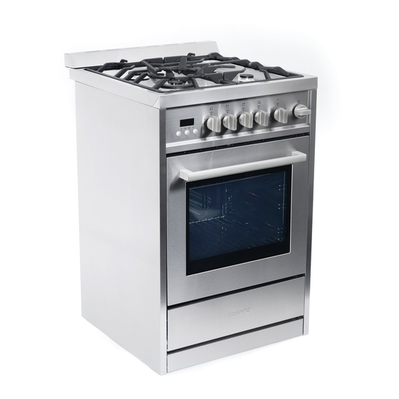
24-INCH FREESTANDING
Cosmo is constantly making efforts to improve the quality and
performance of our products, so we may make changes to our
appliances without updating this manual.
COS-244AGC
GAS RANGE
COS-244AGC
Installation Manual
Manual de instalación
Advertisement
Chapters
Table of Contents

Related Manuals for Cosmo COS-244AGC


Summary of Contents for Cosmo COS-244AGC
- Page 1 I N S P I R I N G T H E W O R L D ’ S K I T C H E N 24-INCH FREESTANDING GAS RANGE COS-244AGC Cosmo is constantly making efforts to improve the quality and performance of our products, so we may make changes to our appliances without updating this manual. Installation Manual COS-244AGC Manual de instalación...
-
Page 2: Table Of Contents
Electrical Requirements COSMO appliances are designed according to the strictest safety and performance Gas Supply Requirements standard for the North American market. We follow the most advanced manu- INSTALLATION INSTRUCTIONS facturing philosophy. -
Page 3: Precautions
PRECAUTIONS PRECAUTIONS Explanation of Symbols: WARNING WARNING CAUTION Tip Over Hazard: Hazards or unsafe practices which Hazards or unsafe practices which • A child or adult can tip the range and be killed. COULD result in severe personal injury COULD result in minor personal injury. •... -
Page 4: Installation Requirements
INSTALLATION REQUIREMENTS LOCATION REQUIREMENTS IMPORTANT: Observe all governing codes and Figure 3 TOOLS AND PARTS ordinances� DO NOT obstruct flow of combustion and ventilation air� Rating Plate Tools Required It is the installer’s responsibility to comply with Gather the necessary tools and parts before starting the installation. Carefully installation clearances specified on the model/serial rating plate�... -
Page 5: Electrical Requirements
Cabinet Dimensions Temperature IMPORTANT: The oven has been designed in accordance with the requirements of UL and CSA International Figure 5 and complies with the maximum allowable wood cabinet temperatures of 194°F (90°C)� CAUTION: Not all cabinet and building materials are designed to withstand the heat produced by the oven for baking and self-cleaning�... -
Page 6: Gas Supply Requirements
NOTE: The metal chassis of the range must be grounded� If the metal chassis is not grounded, the control panel Gas Pressure Regulator will not operate� Check with a qualified technician to ensure the metal chassis of the range is grounded properly� The gas pressure regulator supplied with this range must be used�... -
Page 7: Installation Instructions
INSTALLATION INSTRUCTIONS • Failure to follow these instructions can result in death or serious burns to children and adults� INSTALLATION INSTRUCTION IMPORTANT: DO NOT completely remove the rear leveling leg� The anti-tip bracket uses either the right-hand or left hand, rear leveling leg to secure the range to the floor� IMPORTANT: This appliance SHALL BE installed only by qualified technician and in accordance with the STEP 1: LOCATE THE BRACKET manufacturer’s installation instructions, local gas fitting regulations, municipal building codes, electrical wiring... -
Page 8: How To Connect Gas Line
HOW TO CONNECT GAS LINE How to Complete Gas Connection WARNING: Explosion Hazard 1� Open the manual shut-off valve in the gas supply line� • Use a new CSA International approved gas supply line� • The valve is open when the handle is parallel to the gas pipe� • Install a shut-off valve�... -
Page 9: How To Level The Range
IMPORTANT: If you hear a snapping or popping sound when lifting the range, the range may not be fully How to Adjust Flame Height Figure 16 engaged in the bracket� Check the bracket for obstructions keeping the range from sliding into the wall or keeping Adjust the height of top burner flames�... - Page 10 The conversion must be performed by a qualified technician in accordance with the kit instructions and all local Change Burner Orifices codes/requirements� IMPORTANT: Carefully read and observe each orifice label for correct location� See the Burner Chart earlier in Figure 18 Manual Shut-Off Valve CAUTION: Failure to follow instructions this section�...
- Page 11 5000 Pour tout problème concernant ce produit, veuillez contacter Top Burner 1�40 mm 7900 le service des consommateurs Cosmo Customer Support au Bottom Burner 1�70 mm 10700 1-888-784-3108. UNE PREUVE D’ A CHAT DATEE EST REQUISE POUR BENEFICIER DE LA GARANTIE.
- Page 12 Estufa a Gas Independiente de 24 Pulgadas Manual de instalación LEA ESTE MANUAL ANTES DE UTILIZAR SU ESTUFA A GAS Y GUÁRDELO PARA FUTURA REFERENCIA.
- Page 13 PRECAUCIONES TABLE OF CONTENTS PRECAUCIONES ExPLICACIÓN DE LOS SíMBOLOS PRECAUCIONES ADVERTENCIA Peligros o prácticas inseguras que PODRíAN provocar lesiones personales graves o muerte� REQUISITOS DE INSTALACIÓN PRECAUCIÓN Herramientas y piezas Peligros o prácticas inseguras que PODRíAN provocar lesiones personales leves� ESTE PRODUCTO ES SÓLO PARA USO Requerimientos locales Requisitos eléctricos...
-
Page 14: Requisitos De Instalación
REQUISITOS DE INSTALACIÓN REQUISITOS DE INSTALACIÓN HERRAMIENTAS y PIEzAS ADVERTENCIA: Qué hacer si huele a gas • NO trate de encender ningún aparato� Herramientas requeridas • NO toque ningún interruptor eléctrico� Reúna las herramientas y las piezas necesarias antes de iniciar la instalación� Siga cuidadosamente las instrucciones • NO utilice ningún teléfono en la casa�... -
Page 15: Requerimientos Locales
REQUERIMIENTOS LOCALES Dimensiones de los gabinetes IMPORTANTE: Cumpla con todos los códigos y Figura 3 Figura 5 las ordenanzas aplicables� NO obstruya el flujo de combustión y el aire de ventilación� Placa de Es responsabilidad del instalador cumplir con los espacios clasificación de instalación especificados en la placa de clasificación modelo/serial�... -
Page 16: Requisitos Eléctricos
i� La distancia desde el piso a la parte superior del gabinete: 84-2/5” (213,36 cm) • Los sistemas de encendido electrónico funcionan dentro de amplios límites de voltaje, pero la conexión a tierra y polaridad apropiada son necesarias� Verifique que el tomacorriente proporcione una alimentación Temperatura de 120 voltios y que esté... -
Page 17: Instrucciones De Instalación
Conector de metal flexible para aparato INSTRUCCIONES DE INSTALACIÓN INSTRUCCIONES DE INSTALACIÓN Figura 8 Si los códigos locales lo permiten, puede utilizarse un conector de metal flexible para aparato nuevo, con diseñado-certificado de CSA de 4 a 5 pies (122-152,4 cm) IMPORTANTE: Este aparato DEBE SER instalado únicamente por un técnico calificado y de acuerdo con de largo, diámetro interno de ½”... -
Page 18: Cómo Conectar La Línea De Gas
ADVERTENCIA: Peligro de volcamiento completamente en el soporte ANTI-VOLCADURAS, como se muestra en el Paso 1� Para controlar si el soporte es • Un niño o adulto puede volcar la estufa y resultar muerto� instalado y ajustado de forma apropiada, mire que debajo de la cocina la pata niveladora trasera esté ajustada al soporte�... -
Page 19: Cómo Conectar La Energía Eléctrica
• Esta estufa no requiere ser enchufada a un tomacorriente GFCI (Interruptor de circuito con descarga a Figura 13 tierra)� Se recomienda que usted NO enchufe una estufa a gas de encendido por chispa eléctrica o cualquier otro aparato en un tomacorriente de pared GFCI, dado que esto puede causar que el GFCI se dispare durante el ciclo normal�... -
Page 20: Cómo Verificar El Funcionamiento
2� Colocar una parrilla estándar plana en el horno� Figura 15 Figura 17 3� Coloque el nivel en la parrilla� Vástago de la válvula de la perilla de control 4� Utilice una llave para ajustar las patas niveladoras hacia arriba o hacia abajo hasta que la estufa esté... - Page 21 Cortar el suministro a la Estufa NOTA: El quemador triple sólo tiene dos inyectores, un inyector instalado en el centro y otro instalado debajo de Figura 18 Válvula de cierre manual la tapa� Para tener acceso al segundo inyector, retire los dos tornillos y la tapa� 1�...
- Page 22 5000 Pour tout problème concernant ce produit, veuillez contacter Quemador superior 1,40 mm 7900 le service des consommateurs Cosmo Customer Support au Quemador de la parte inferior 1,70 mm 10700 1-888-784-3108. Tipo de gas: Punto de toma de presión GPL 10”...
- Page 23 Electronic version of this manual is available at: www.cosmoappliances.com...
Need help?
Do you have a question about the COS-244AGC and is the answer not in the manual?
Questions and answers
Which side of the stove does the gas line hook to?
The gas line connects to the rear of the Cosmo COS-244AGC stove and should be located in the same room but external to the range. The exact side is not specified.
This answer is automatically generated