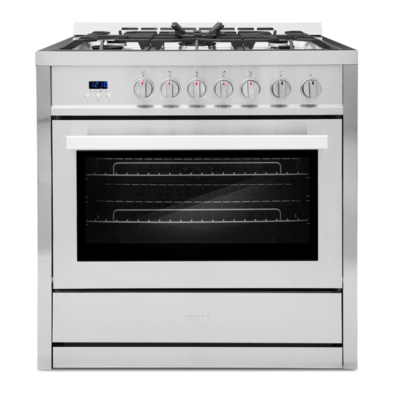
Cosmo COS-965AGC Installation Manual
36 in. professional style range
Hide thumbs
Also See for COS-965AGC:
- User manual ,
- Installation manual (42 pages) ,
- Installation instructions manual (90 pages)

Related Manuals for Cosmo COS-965AGC


Summary of Contents for Cosmo COS-965AGC
- Page 1 GAS RANGE COS-965AGC COS-965AGFC 36 in. Professional Style Range Installation Manual IMPORTANT: Read and save these instructions. NOTICE: Installer: Leave this guide with the homeowner Homeowner: Keep this guide for future reference...
- Page 2 COSMO Appliances are designed according to the strictest safety and performance standard for the North American market. We follow the most advanced manufacturing philosophy.
-
Page 3: Table Of Contents
TABLE OF CONTENTS RANGE SAFETY .................4 INSTALLATION REQUIREMENTS ..........8 Tools and Parts ................8 Location Requirements ..............10 Electrical Requirements .............13 Gas Supply Requirements ............16 INSTALLATION INSTRUCTIONS ..........19 Step 1 - Unpack Range .............19 Step 2 - Make Gas Connection ..........23 Step 3 - Make Electrical Connection .........25 Step 4 - Install Range ..............25 Step 5 - Level the Range (if needed) .........26 Step 6 - Check Operation of Electronic Ignition System ..27... -
Page 4: Range Safety
RANGE SAFETY WARNING A child or adult can tip the range and be killed. Install the anti-tip device to the structure and / or the range. Verify the anti-tip device has been properly installed and engaged. Engage the range to the anti-tip device. Ensure the anti-tip device is re-engaged when the range is moved. - Page 5 Your safety and the safety of others are very important. We have provided many important safety messages in this manual and on your appliance. Always read and obey all safety messages. This is the safety alert symbol. This symbol alerts you to potential hazards that can kill or hurt you and others.
- Page 6 WARNING Fire Hazard If the information in this manual is not followed exactly, a fire or explosion may result causing property damage, personal injury or death. - Do not store or use gasoline or other ammable vapors and liquids in the vicinity of this or any other appliance. - WHAT TO DO IF YOU SMELL GAS •...
- Page 7 In the State of Massachusetts, the following installation instructions apply: • Installations and repairs must be performed by a qualified or licensed contractor, plumber, or gasfitter qualified or licensed by the State of Massachusetts. • If using a ball valve, it shall be a T-handle type. A flexible gas connector, when used, must not exceed 3 •...
-
Page 8: Installation Requirements
INSTALLATION REQUIREMENTS TOOLS AND PARTS Gather the required tools and parts before starting installation. Read and follow the instructions provided with any tools listed here. TOOLS NEEDED Tape measure • 3/8" nut driver • Flat-blade screwdriver • 1/4" nut driver •... - Page 9 • 7 mm combination wrench • PARTS SUPPLIED Check that all parts are included. COS-965AGC ONLY PARTS NEEDED Check local codes and consult gas supplier. Check existing gas supply and electrical supply. See "Electrical Requirements" and "Gas Supply Requirements" sections.
-
Page 10: Location Requirements
LOCATION REQUIREMENTS VENTILATION Observe all governing codes and ordinances. Do not obstruct flow of IMPORTANT: combustion and ventilation air. • It is the installer’s responsibility to comply with installation clearances specified on the model/serial rating plate. The model/serial rating plate is located on the left-hand side of the oven frame. - Page 11 DIMENSIONS Freestanding Range Model Size 6.0" 6.0" 35.6" 25" 36" (15cm) (15cm) (90.5cm) (63.5cm) Warning: Cabinets 13 in. deep and not less than the nominal width of the appliance must be installed at least 30 in. above the cooking surface. Cabinets maximum 13 in.
- Page 12 Back of Range Power Supply IMPORTANT: An electrical outlet in the floor, may be either recessed or surface mounted, but an electrical outlet in the wall must be recessed to make the connection. 3" (7.6 cm) (90cm) 17½" (44 cm) 11½"...
-
Page 13: Electrical Requirements
ELECTRICAL REQUIREMENTS WARNING Electrical Shock Hazard Plug into a grounded 3 prong outlet. Do not remove the ground prong from the power cord plug. Do not use an adapter. Do not use an extension cord. IMPORTANT: The range must be electrically grounded in accordance with local codes and ordinances, or in the absence of local codes, with the National Electrical Code, ANSI/NFPA 70 or Canadian Electrical Code, CSA C22.1. - Page 14 A copy of the above code standards can be obtained from: National Fire Protection Association 1 Batterymarch Park Quincy, MA 02169-7471 CSA International 8501 East Pleasant Valley Road Cleveland, OH 44131-5575 • A 120 volt, 60 Hz., AC only, 15-amp fused, electrical circuit is required. A time- delay fuse or circuit breaker is also recommended.
- Page 15 Verify proper operation after servicing. Attention: Étiqueter tous les fils avant de les débrancher pour effectuer l’entretien des régulateurs. Une erreur de câblage peut entraîner une utilisation inappropriée ou dangereuse. S’assurer du bon fonctionnement de l’appareil après l’entretien. COS-965AGC COS-965AGFC...
-
Page 16: Gas Supply Requirements
GAS SUPPLY REQUIREMENTS WARNING Explosion Hazard Use a new CSA International approved gas supply line. Install a shut-off valve. Securely tighten all gas connections. does not exceed 14" (36 cm) water column. licensed heating personnel, authorized gas company personnel, and authorized service personnel. - Page 17 LP gas conversion: IMPORTANT: Conversion must be done by a qualified service technician. No attempt shall be made to convert the appliance from the gas specified on the model/serial rating plate for use with a different gas without consulting the serving gas supplier.
- Page 18 Rigid pipe connection: The rigid pipe connection requires a combination of pipe fittings to obtain an in- line connection to the range. The rigid pipe must be level with the range connection. All strains must be removed from the supply and fuel lines so range will be level and in line.
-
Page 19: Installation Instructions
INSTALLATION INSTRUCTIONS IMPORTANT: This appliance shall be installed only by authorized persons and in accordance with the manufacturer’s installation instructions, local gas fitting regulations, municipal building codes, electrical wiring regulations, local water supply regulations. STEP 1 - UNPACK RANGE WARNING Excessive Weight Hazard Use two or more people to move and install range. - Page 20 INSTALL ANTI-TIP BRACKET (For COS-965AGC Only) WARNING Tip Over Hazard A child or adult can tip the range and be killed. Connect anti-tip bracket to rear range foot. Reconnect the anti-tip bracket, if the range is moved. See the installation instructions for details.
- Page 21 3. Using the anti-tip bracket as a template, mark the two holes for either a Floor Wood, Floor Concrete, or Wall installation, as shown. Distance from Adjacent Cabinet (³⁄₈" to ¹⁄₂" [0.95 to 1.27 cm]) Wall Holes Concrete Floor Holes Wood Floor Holes Rear Range Foot 4.
- Page 22 INSTALLING THE ANTI-TIP CHAIN (For COS-965AGFC Only) The range is supplied with anti- tipping chains prevent appliance from tilting forward and accidental damage to the gas pipe. 1. Take the wall anchor with hook that was included with your unit and drill an adequate hole in the wall behind, at the same height as the chain.
-
Page 23: Step 2 - Make Gas Connection
STEP 2 - MAKE GAS CONNECTION WARNING Explosion Hazard Use a new CSA International approved gas supply line. Install a shut-off valve. Securely tighten all gas connections. If connected to LP, have a quali ed person make sure gas pressure does not exceed 14"... - Page 24 CONNECT GAS LINE FROM GAS PRESSURE REGULATOR TO GAS SUPPLY: 1. Apply pipe-joint compound made for use with LP gas to the tapered (NPT) threads of both adapters supplied with gas line kit. 2. Attach one adapter to the gas pressure regulator and the other to the gas NOTE: Do Not rotate the gas pressure regulator.
-
Page 25: Step 3 - Make Electrical Connection
STEP 3 - MAKE ELECTRICAL CONNECTION WARNING Electrical Shock Hazard Plug into a grounded 3 prong outlet. Do not remove the ground prong from the power cord plug. Do not use an adapter. Do not use an extension cord. Failure to do so can result in death, re or electrical shock. 1. -
Page 26: Step 5 - Level The Range (If Needed)
3. Slowly attempt to tilt the range forward. If you encounter immediate resistance, the range foot is engaged in the anti-tip bracket. Go to Step 8. 4. If the rear of the range lifts more than 1/2" (1.3 cm) off the floor without resistance, stop tilting the range and lower it gently back to the floor. -
Page 27: Step 6 - Check Operation Of Electronic Ignition System
STEP 6 - CHECK OPERATION OF ELECTRONIC IGNITION SYSTEM The cooktop and oven burners use electronic igniters in place of standing pilots. When the cooktop control knob is turned to the “ICON” position, the system creates a spark to light the burner. This sparking continues, as long as the control knob is turned to “ICON.”... -
Page 28: Gas Conversion
If the low flame needs to be adjusted: Adjustment Screw Control Knob Stem 1. Light one burner and turn the control knob to the lowest setting. 2. Remove the control knob. 3. Insert a small, flat-blade screwdriver into the adjustment screw, and slowly turn the screw until the flame appearance is correct. - Page 29 Ignite the burner of oven 1. Set the working time in timer first; 2. Push and turn the knob to ignite; a) Turn the knob clockwise to "Broil" to indicate ignition of the upper bar. b) Turn the Knob counter -clockwise to any scale of temperature to indicate ignition of the lower burner.
- Page 30 LP/PROPANE GAS CONVERSION This appliance can be used with Natural Gas or LP/Propane gas. It is shipped from the factory for use with natural gas. A kit for converting to LP gas is supplied with your cooktop. The kit is marked “FOR LP/PROPANE GAS CONVERSION”. When the cooktop is converted for liquid petroleum (LP) gas, the LP gas supply is required to provide a minimum of 10"...
- Page 31 36" Burner and Orifice Characteristic Table (M-A) Manifold Orifice Rate Pressure Burner Diam. (mm) Type [i.w.c.] [BTU/h] 18000 4" Triplering 17000 1.22 LP (Propane) 10" 1.45 4" 8800 Rapid 0.91 LP (Propane) 10" 8800 1.29 4" 6900 Semi-Rapid LP (Propane) 10"...
-
Page 32: Step 1 - Adjust The Regulator
STEP 1 - ADJUST THE REGULATOR IMPORTANT: Disconnect all electrical power, at the main circuit breaker or fuse box. Shut off the gas supply to the range by closing the manual shut-off valve. 1. Unscrew the regulator cap with the wrench. Regulator Cap 2. -
Page 33: Step 2 - Change Burner Orifices
4. Screw the regulator cap back into the regulator and reattach the regulator to the STEP 2 - CHANGE BURNER ORIFICES IMPORTANT: the Burner Chart earlier in this section. NOTE: possibility that some may not be replaced. 1. Remove the burner grates, burner caps and burner heads. Triple Ring Burner Auxiliary Burner Semi-Rapid Burner... - Page 34 Properly Seated Not Properly Seated Check air tightness: 1. Smear the joint with soapy water. 2. Open the air path and observe whether there is air leakage at the joint (soapy water bubbles out, indicating there is air leakage) Note: Make sure there is no air leakage before use.
-
Page 35: Step 3 - Adjust Burner Flames
STEP 3 - ADJUST BURNER FLAMES NOTES: • Turn all burners on highest setting and check the flames. They should be blue in color and may have some yellow tipping at the ends of the flame when using LP gas. Foreign particles in the gas line may cause an orange flame at first, but this will soon disappear. -
Page 36: Step 4 - Testing Flame Stability
2. Remove the control knob. 3. Insert a small, flat-blade screwdriver into the adjustment screw, and slowly turn the screw until the flame appearance is correct. • Open the valve more if the flames are too small or fluttered. • Close the valve more if the flames are too large. - Page 37 WARRANTY AND SERVICE For full warranty details on this product please visit: http://www.cosmoappliances.com/warranty TO RECEIVE WARRANTY SERVICE, YOUR PRODUCT MUST BE REGISTERED. TO REGISTER, VISIT: WWW.COSMOAPPLIANCES.COM/WARRANTY SCAN TO REGISTER...
- Page 38 REQUIRED FOR WARRANTY SERVICE IMPORTANT Ne pas Réexpédier ce Produit au Magasin Pour tout problème concernant ce produit, veuillez contacter le service des consommateurs Cosmo Customer Support au +1(888) 784-3108 UNE PREUVE D’ A CHAT DATEE EST REQUISE POUR BENEFICIER DE LA GARANTIE.
- Page 39 NOTE:...
- Page 40 Cosmo is constantly making efforts to improve the quality and performance of our products, so we may make changes to our appliances without updating this manual. Electronic version of this manual is available at: www.cosmoappliances.com...
Need help?
Do you have a question about the COS-965AGC and is the answer not in the manual?
Questions and answers