
Related Manuals for Taurus Stair Trainer ST10.5


Summary of Contents for Taurus Stair Trainer ST10.5
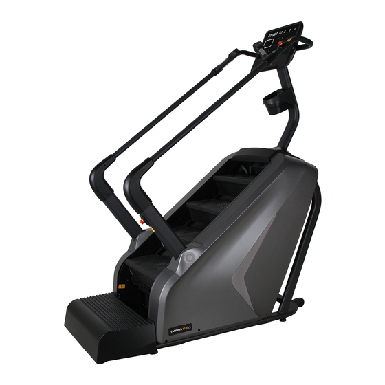
- Page 1 Assembly and Operating Instructions max. 180 kg ~ 60 Min. 185 kg L 176 | W 80 | H 211 FSTFST105.01.02 Art.-No. TF-ST105 Taurus Stair Trainer ST10.5...
- Page 2 ST10.5...
-
Page 3: Table Of Contents
Content GENERAL INFORMATION Technical Data Personal Safety Electrical Safety Set-Up Place ASSEMBLY General Instructions Scope of Delivery Assembly OPERATING INSTRUCTIONS Console Display Button Functions Turning On the Equipment and Initial Settings Training Programmes 3.4.1 Quick Start (MANUAL) 3.4.2 Countdown Programmes (HEIGHT, CALORIES, TIME) 3.4.3 Pre-set Programmes (PROG.) 3.4.4 User-defi ned Programmes (CUSTOM) Body Mass Index (FAT) - Page 4 ORDERING SPARE PARTS Serial Number and Model Name Parts List Exploded Drawing WARRANTY CONTACT ST10.5...
- Page 5 European VAT Number: DE813211547 Disclaimer © TAURUS is a registered brand of the company Fitshop GmbH. All rights reserved. Any use of this trademark without the explicit written permission of Fitshop is prohibited. Product and manual are subject to change. Technical data can be changed without advance notice.
- Page 6 ABOUT THIS MANUAL Please carefully read the entire manual before installation and fi rst use. The manual will help you to quickly set up the system and explains how to safely use it. Make sure that all persons exercising with the equipment (especially children and persons with physical, sensory, mental or motor disabilities) are informed about this manual and its contents in advance.
- Page 7 Please pay close attention to the safety and maintenance instructions given here. The contract partner cannot be held liable for damage to health, accidents or damage to the equipment when it is not used in accordance with these instructions. The following safety instructions may appear in this manual: ATTENTION This notice indicates potentially hazardous situations which, if not avoided, may result in property damage.
-
Page 8: General Information
GENERAL INFORMATION Technical Data LED Display Training time in minutes Speed in levels Distance/height in metres Calories in kcal Pulse in beats per minute (when using the hand pulse sensors or a compatible chest strap) Steps Pace in steps per minute Pre-set programmes: Target programmes: Customized programmes:... -
Page 9: Personal Safety
Personal Safety ⚠ DANGER Before you start using the equipment, you should consult your physician that this type of exercise is suitable for you from a health perspective. Particularly aff ected are persons who: have a hereditary disposition to high blood pressure or heart disease, are over the age of 45, smoke, have high cholesterol values, are overweight and/or have not exercised regularly in the past year. -
Page 10: Electrical Safety
ATTENTION Do not insert any objects of any kind into the openings of the device. To protect the equipment from use by unauthorised third parties, always remove the power cable (if existing) when not in use and store it in a safe place that is inaccessible to unauthorised persons (e.g. -
Page 11: Set-Up Place
Set-Up Place ⚠ WARNING Do not place the equipment in main corridors or escape routes. ⚠ CAUTION Make sure that there is a safety area behind the treadmill with a length of at least 2 m and a width at least equal to the width of the treadmill. The training room should be well ventilated during training and not be exposed to any draughts. -
Page 12: Assembly
ASSEMBLY General Instructions ⚠ DANGER Do not leave any tools, packaging materials such as foils or small parts lying around, as otherwise there is a danger of suff ocation for children. Keep children away from the equipment during assembly. Pay attention to the instructions attached to the equipment in order to reduce the risk of injuries. - Page 13 4: Rear Handrail 5: Console Support Column 41L/R: Left and Right 47: Console 1: Main Frame #41L/R Decorative Cover 44L/R: Left and Right 45L/R: Left and Right 2L: Right #44L/R #45L/R Exterior Decorative Interior Decorative Support Column Cover Cover 3L/R: Left and Right 2R: Right Support 40: Pedal 58: Decorative Cover...
-
Page 14: Assembly
Assembly Before assembly, take a close look at the individual assembly steps shown and carry out the assembly in the order given. NOTICE First loosely screw all parts together and check that they fi t properly. Tighten the screws using the tool only when you are instructed to do so. - Page 15 Step 2: Assembly of the Support Column and Decorative Cover ATTENTION Make sure not to pinch the cables during the following steps. Connect the console extension wire (104) to the lower wire (105). NOTICE Do not fully tighten the screws yet in the following step. Attach the support column (5) to the main frame (1) with four screws (68) and four washers (95).
- Page 16 Step 3: Assembly of the Support Columns, Handrails and Decorative Covers Slide the left and right decorative covers (41L & 41R) onto the left and right support columns (2L & 2R). ATTENTION Make sure not to pinch the cables during the following steps. Carefully pass the switch upper wire 1 (106) through the right decorative cover (41R).
- Page 17 Step 4: Assembly of the Rear Handrail and Decorative Covers Connect the pulse extension wire 1 (111) to the pulse extension wire 2 (112). Connect the key board extension wire 1 (115) to the key board extension wire 2 (116). Repeat the steps on the other side.
- Page 18 ST10.5...
- Page 19 Step 5: Assembly of the Console and Bottle Holder Connect the wires of the console (47) with their respective components on the rear handrail (4) and support column (5). ATTENTION Make sure not to pinch the cables during the following steps. Attach the console (47) to the support column (5) with four screws (78).
- Page 20 ST10.5...
- Page 21 Step 6: Alignment of the Feet If the fl oor is uneven, you can stabilize the stair trainer by turning the two setting screws under the main frame. Lift the stair trainer on the desired side and rotate the setting screws under the main frame. Rotate the screws clockwise in order to raise the surface.
-
Page 22: Operating Instructions
OPERATING INSTRUCTIONS NOTICE Familiarise yourself with all the functions and setting options of the device before starting training. Have the proper use of this product explained to you by a specialist. Always start your training with low intensity and increase evenly and gently. End your training with a cool-down phase. - Page 23 Display of calorie consumption in kcal Display range: 0-999 Setting range: 10.0-999 Default setting value: 50.0 Calories NOTICE These data serve as a rough guide for comparing training sessions. They must not be used for medical purposes. Display of the current speed in level Display range: 1-25 Level Setting range: 1-25...
-
Page 24: Button Functions
Button Functions Decrease and increase speed level by 1 Display of training data Quick keys for speed level Music volume Setting Programme selection Start/Pause Stop adjustment adjustment training training Previous/next song Start Cool Down Keypad START/PAUSE Press to start and pause training STOP Press to stop training Press + to increase setting value by 1... - Page 25 PREVIOUS SONG Press to skip to the previous song NEXT SONG Press to skip to the next song Press during training to start cool down A countdown of 30 or 45 seconds starts When speed is set between 1 and 15, the machine stops COOL DOWN within 30 seconds When speed is set between 16 and 25, the machine stops...
- Page 26 Four buttons for the most important functions have been integrated on the handles for easier operation during training. The buttons for “start/pause” and “stop” are located on the left handle. The buttons for speed increase and decrease are located on the right handle. The machine is also equipped with two red emergeny stop switches that are located near the right handle and on the right support column at the bottom of the machine.
- Page 27 NOTICE Please note that smartphones are compatible for wireless charging. USB port to read audio and video data Wireless charging function for smartphones Audio output for headphones Emergency stop switch Infrared sensing area Emergency stop switch...
-
Page 28: Turning On The Equipment And Initial Settings
Turning On the Equipment and Initial Settings Insert the power plug into a wall outlet. Turn on the power switch. Unscrew the two emergency stop switches. Check that the infrared sensing area is free of obstructions. ⚠ WARNING The infrared sensing area must always be free of obstructions when you stand on the equipment. Infrared Sensing Area If an object enters the infrared sensing area during operation, the machine will immediately stop, an error message occurs in the display and an alarm sounds. -
Page 29: Training Programmes
Training Programmes The console off ers a wide variety of diff erent training options and programmes. These include a quick start function for immediate training, countdown programmes, pre-set programmes and user defi ned programmes. 3.4.1 Quick Start (MANUAL) The quick start function is the ideal choice if you want to start your training immediately and without setting any specifi c training data. -
Page 30: Countdown Programmes (Height, Calories, Time)
3.4.2 Countdown Programmes (HEIGHT, CALORIES, TIME) There are three so-called target or countdown programmes in which you can set a target value for either height, calories or time. The programme will start a countdown from the set target value and ends automatically when you have reached your goal. -
Page 31: Pre-Set Programmes (Prog.)
3.4.3 Pre-set Programmes (PROG.) There are 36 pre-set programmes (P01 - P36) to choose from. Contrary to the quick start function, these programmes have pre-set speed levels that vary within the set training time. Each programme consists of 20 segments. The duration of each segment depends on the training time. To calculate the duration of each segment, the training time must be divided by 20. - Page 32 The drawing below shows the profi les of each of the pre-set programmes. With this drawing you can see which speed level is pre-set for each of the 20 segments within the 36 pre-set programmes. P1 - P36: Pre-Set programmes S1 - S20: Segment 1 to 20 ST10.5...
-
Page 33: User-Defi Ned Programmes (Custom)
3.4.4 User-defi ned Programmes (CUSTOM) The user-defi ned programmes allow users to customize their own profi le programme. The concept is similar to the pre-set programmes, except that users can individually defi ne the speed level from 1 to 25 for each segment in the programme. There are a total of three customizable programmes (U01-U03). -
Page 34: Body Mass Index (Fat)
Body Mass Index (FAT) The console is equipped with an in-built Body Mass Index (in short: BMI) calculator. BMI can be used to measure a person’s height and weight in relation to one another. ⚠ WARNING This data is for reference only and must not be considered as medical data. The BMI calculation does not distinguish between fat or muscle mass. -
Page 35: Storage And Transport
STORAGE AND TRANSPORT General Instructions ⚠ WARNING The storage location should be chosen so that improper use by third parties or children can be prevented. If your equipment does not have transportation wheels, the equipment must be disassembled before transportation. ATTENTION Make sure that the equipment is protected from moisture, dust and dirt in the selected storage location. -
Page 36: Troubleshooting, Care And Maintenance
TROUBLESHOOTING, CARE AND MAINTENANCE General Instructions ⚠ WARNING Do not make any improper changes to the equipment. ⚠ CAUTION Damaged or worn components may aff ect your safety and the life of the equipment. Therefore, immediately replace damaged or worn components. In such a case, contact the contract partner. -
Page 37: Error Codes And Troubleshooting
Error Codes and Troubleshooting The electronics of the equipment continuously carries out tests. In case of deviations, an error code appears on the display and normal operation is stopped for your safety. E80/E01: Communication failure E02: Communication failure E08: Lower control infrared failure E48: No speed sensing signal Please contact the contract partner for technical support. -
Page 38: Maintenance And Inspection Calendar
Maintenance and Inspection Calendar To avoid damage from body sweat, the equipment must be cleaned with a damp towel (no solvents!) after each training session. The following routine tasks must be performed at the specifi ed intervals: Part Weekly Monthly Quarterly Display console Steps... -
Page 39: Recommended Accessories
RECOMMENDED ACCESSORIES To make your training experience even more effi cient and pleasant, we recommend that you add suiting accessories to your fi tness equipment. For stair trainers this could for example be a fl oor mat, which makes your fi tness equipment stand more securely and also protects the fl oor from sweat or silicone spray to keep moving parts in good shape and lubricate the chains. -
Page 40: Ordering Spare Parts
The serial number of your equipment is unique. It's located on a white sticker. The exact position of this sticker is shown in the following illustration. Enter the serial number in the appropriate fi eld. Serial number: Brand / Category: Taurus / stair trainer Model Name: Stair Trainer ST10.5 Article Number: TF-ST105... -
Page 41: Parts List
Parts List Name Qty. Name Qty. Main frame KP005 pedestal bearing 2L/R Support columns 1 p.r. brake combination 3L/R Handrails 1p.r. 34L/R Protective cover 1p.r Rear handrail 35L/R Inner protective cover 1p.r Console support column 36L/R Decorative strips 1p.r Rear pedal Upper protective cover Front roller Upper protective cover 2... - Page 42 Roller E-type snap ring Φ 7 Allen bolt M10 * 40 Internal serrated washer Φ 10*1.2 Allen bolt M10 * 170 Internal serrated washer Φ Outer hexagon bolt M10 * 45 8*1.2 Allen bolt M10 * 30 Standard spring washer Φ 10 4 Allen bolt M10 * 20 standard fl at washer Φ...
-
Page 43: Exploded Drawing
Exploded Drawing... -
Page 44: Warranty
WARRANTY Products from TAURUS® are subject to strict quality control. However, if a fi tness equipment purchased from us does not work perfectly, we take it very seriously and ask you to contact our customer service as indicated. We are happy to help you by phone via our service hotline. - Page 45 Warranty Conditions For the warranty to be valid, the following steps must be taken: Please contact our customer service by email or phone. If the product under warranty has to be sent in for repair, the seller bears costs. After expiry of the warranty, the buyer bears the costs of transport and insurance.
-
Page 46: Contact
CONTACT TECHNIK TEKNIK OG SERVICE CUSTOMER SUPPORT �� �� �� +49 4621 4210-900 80 90 16 50 00800 2020 2772 +494621 4210 944 +49 4621 4210-945 �� +49 4621 4210-698 �� �� info@fi tshop.dk info@fi tshop.co.uk �� technik@fi tshop.de �� ��... - Page 47 LIVE FITNESS WEBSHOP AND SOCIAL MEDIA Fitshop is Europe’s largest specialist store for www.fi tshop.co.uk home fi tness equipment with currently over 70 www.fi tshop.de/blog stores and one of the world’s most renowned online mail order companies for fi tness equipment.
- Page 48 Notes ST10.5...
- Page 49 Notes...
- Page 50 Notes ST10.5...
- Page 52 Taurus Stair Trainer ST10.5...
Need help?
Do you have a question about the Stair Trainer ST10.5 and is the answer not in the manual?
Questions and answers