
Related Manuals for ASROCK Rack 1U2E Series


Summary of Contents for ASROCK Rack 1U2E Series
- Page 1 1U2E Series User Manual Version 1.0 Published March 2022 Copyright©2022 ASRock Rack INC. All rights reserved.
- Page 2 In no event shall ASRock Rack, its directors, officers, employees, or agents be liable for any indirect, special, incidental, or consequential damages (including damages for loss of profits, loss of business, loss of data, interruption of business and the like), even if ASRock Rack has been advised of the possibility of such damages arising from any defect or error in the documentation or product.
- Page 3 Setting up the Server in a Restricted Access Location • Access can only be gained by service persons or by users who have been instructed about the reasons for the restrictions applied to the location and about any precautions that shall be taken. • Access is through the use of a tool or lock and key, or other means of security, and is controlled by the authority responsible for the location.
-
Page 4: Table Of Contents
Contents Chapter 1 Introduction Shipping Box Contents Specifications Chapter 2 Server System Overview System Components Internal Features System Front Panel System Rear Panel Front Control Panel Buttons and LEDs Drive Tray LEDs Chapter 3 Hardware Installation and Maintenance Server Top Cover 3.5”... - Page 5 Appendix B Installation of Memory Modules (DIMM) Appendix C Block Diagram (E3C252D4U) Block Diagram (X570D4U)
-
Page 7: Chapter 1 Introduction
In case any modifications of this documentation occur, the updated version will be available on ASRock Rack’s website without further notice. If you require technical support related to this product, please visit our website for specific information about the model you are using. -
Page 8: Specifications
1.2 Specifications 1U2E Series System Physical Status Form Factor 1U Rackmount Dimension 393.2 x 430 x 43.5 mm (15.5'' x 16.93'' x 1.71'') (D x W x H) Support MB Size mATX (E3C252D4U / X570D4U) Front Panel Button • Power On button •... -
Page 9: Chapter 2 Server System Overview
1U2E Series Chapter 2 Server System Overview This chapter provides diagrams showing the location of important components of the server system. 2.1 System Components 1 x Power Supply Unit 1 x Hot-Swap HDD Fan Server Board 2 x 2.5” NVME/SATA HDD Trays... -
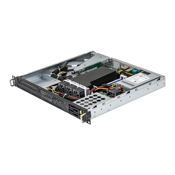
Page 10: Internal Features
2.2 Internal Features From 1 x Riser Card Mounting Bracket (RB1U4SL_G4_RDV riser card installed) Serverboard 1 x Power Supply Unit (PSU) System Fan 1 (FAN1) System Fan 4 (FAN4) System Fan 3 (FAN3) System Fan 2 (FAN2) 3.5" SATA HDD (HDD2) or Slim ODD (optional) Front Panel Board (FPB) 2 x 2.5"... -
Page 11: System Front Panel
1U2E Series 2.3 System Front Panel HDD0 HDD1 Description 1 x Slim Optical Disk Drive (ODD) (optional) Control Panel Buttons and LEDs 2 x USB 2.0 Ports 2 x 2.5" SATA/NVME HDD Trays 2.4 System Rear Panel Description 1 x Power Supply Unit... -
Page 12: Front Control Panel Buttons And Leds
2.5 Front Control Panel Buttons and LEDs Front Control Panel Description Power Button Power Status LED HDD Status LED LAN1 Activity LED LAN2 Activity LED System Status LED System Reset Button USB 2.0 Port (USB_1) USB 2.0 Port (USB_2) *Please be noted that the functions are supported depending on the type of the server board. There are two push buttons located on the front of the chassis. - Page 13 1U2E Series Power LED Status Description Blue Power on Power off HDD Status LED Status Description Blinking Yellow HDD access HDD idle LAN1 LED Status Description Blue Link between system and network or no access Blinking Blue Network access LAN2 LED...
-
Page 14: Drive Tray Leds
2.6 Drive Tray LEDs Two LEDs are located on each 2.5" HDD tray. These are a hard disk drive activity LED and a hard disk drive status indicator LED (in order from top to bottom). Description HDD ACT LED HDD STATUS LED Status LED Definitions HDD ACT LED Status... -
Page 15: Chapter 3 Hardware Installation And Maintenance
1U2E Series Chapter 3 Hardware Installation and Maintenance This chapter helps you assemble the chassis and install components. Before You Begin Before you work with the server, pay close attention to the “Important Safety Instructions” at the beginning of this manual. -
Page 16: Server Top Cover
3.1 Server Top Cover Removing the Server Top Cover 1. Before removing the top cover, power off the server and unplug the power cord. 2. The system must be operated with the chassis top cover installed to ensure proper cooling. 1. - Page 17 1U2E Series Installing the Server Top Cover 1. Lower the top cover on the chassis, making sure the side latches align with the cutouts. 2. Slide the top cover toward the front. 3. Secure the top cover with the screws.
-
Page 18: Hard Drive
3.2 3.5” Hard Drive Removing a 3.5” Hard Drive Carrier from the Chassis 1. Release the screws that secure the hard drive carrier to the chassis. 2. Lift up and remove the carrier. - Page 19 1U2E Series Installing a 3.5” Hard Drive to the Hard Drive Carrier 1. Place the 3.5" HDD into the carrier with the printed circuit board side facing down. Carefully align the mounting holes in the hard drive and the carrier.
-
Page 20: Hard Drive
3.3 2.5” Hard Drive The system supports 2.5" hard drives. Two 2.5" hard drive trays are located on the front of the system. Removing 2.5” Hard Drive Trays from the Chassis 1. Press the locking lever latch on the drive tray to unlock the retention lever. 2. - Page 21 1U2E Series Installing a 2.5” Hard Drive to the Hard Drive Tray 1. Place a 2.5" HDD into the bracket with the printed circuit board side facing down. 2. Slide the drive tray into the HDD bay until the drive is fully seated.
-
Page 22: System Fan
3.4 System Fan System fans are required for the cooling in the system. Please make sure that the chassis top cover is properly installed in order for the cooling air to circulate properly through the chassis and cool the system and components. If a fan fails, the ambient air temperature in the chassis will rise. -
Page 23: Power Supply
1U2E Series 3.5 Power Supply This system has a single 315 watt power supply and can accommodate one AC power supply in the bay at the rear of the chassis. If the power supply unit fails, the system will shut down and you will need to replace the power supply unit. -
Page 24: Slim Optical Drive (Optional)
3.6 Slim Optical Drive (optional) Removing the Optical Drive Carrier and the Blanking Plate from the Chassis 1. Release the screws that secure the optical drive carrier to the chassis. 2. Lift up and remove the carrier. - Page 25 1U2E Series 3. Release the screws that secure the dust filter blanking plate to the chassis. 4. Push to remove the blanking plate and keep it for reassembly.
- Page 26 Installing an Optical Drive to the Chassis To use a slim optical drive, you need to purchase a rear SATA/Power adapter seperately. Before installation, secure the rear adapter to the bare drive with screws. Place the slim optical drive into the carrier with the connector end toward the rear side of the carrier where the mounting holes are located.
- Page 27 1U2E Series Place the optical drive assembly back to the chassis with screw holes aligned. Secure the ptical drive assembly to the chassis with two screws.
-
Page 28: Installing The Cpu (Lga 1200 Socket)
Appendix A Installing the CPU (LGA 1200 Socket) 1. Before you insert the 1200-Pin CPU into the socket, please check if the PnP cap is on the socket, if the CPU surface is unclean, or if there are any bent pins in the socket. Do not force to insert the CPU into the socket if above situation is found. - Page 29 1U2E Series Please save and replace the cover if the processor is removed. The cover must be placed if you wish to return the motherboard for after service.
-
Page 30: Installing The Cpu Fan And Heatsink (Lga 1200 Socket)
Installing the CPU Fan and Heatsink (LGA 1200 Socket) -
Page 31: Installing The Cpu (Amd Am4 Socket)
1U2E Series Installing the CPU (AMD AM4 Socket) -
Page 33: Installing The Cpu Fan And Heatsink (Amd Am4 Socket)
1U2E Series Installing the CPU Fan and Heatsink (AMD AM4 Socket) After you install the CPU into this motherboard, it is necessary to install a larger heatsink and cooling fan to dissipate heat. You also need to spray thermal grease between the CPU and the heatsink to improve heat dissipation. - Page 35 1U2E Series...
- Page 36 Appendix B Installation of Memory Modules (DIMM) The DIMM only fits in one correct orientation. It will cause permanent damage to the motherboard and the DIMM if you force the DIMM into the slot at incorrect orientation. For more information about DIMM installation, please refer to the User Manual that comes with the serverboard you use.
- Page 37 1U2E Series Appendix C Block Diagram (E3C252D4U) Tatlow Platform PCI-E Gen4 X16 DDR4 2666/2933/3200(ECC/non-ECC) Channel A DDR4 2666/2933/3200(ECC/non-ECC) PCI-E X16 SLOT (x16/x8x8/x8x4x4) PCIE6 DDR4 2666/2933/3200(ECC/non-ECC) Channel B INTEL DDR4 2666/2933/3200(ECC/non-ECC) Rocket Lake-S CPU PCI-E X4(X4)SLOT PCIE x4 gen4 HDMI PCIE4...
- Page 38 Block Diagram (X570D4U)
Need help?
Do you have a question about the 1U2E Series and is the answer not in the manual?
Questions and answers