
Related Manuals for ASROCK Rack 1U2S-B650


Summary of Contents for ASROCK Rack 1U2S-B650
- Page 1 1U2S-B650 User Manual Version 1.0 Published May 2023 Copyright©2023 ASRock Rack INC. All rights reserved.
- Page 2 In no event shall ASRock Rack, its directors, officers, employees, or agents be liable for any indirect, special, incidental, or consequential damages (including damages for loss of...
- Page 3 Setting up the Server in a Restricted Access Location • Access can only be gained by service persons or by users who have been instructed about the reasons for the restrictions applied to the location and about any precautions that shall be taken. •...
-
Page 4: Table Of Contents
Contents Chapter 1 Introduction Shipping Box Contents Specifications Chapter 2 Server System Overview System Components Internal Features System Front Panel System Rear Panel Front Control Panel Buttons and LEDs Drive Tray LEDs Chapter 3 Hardware Installation and Maintenance Server Top Cover 3.5”... - Page 5 Appendix C Block Diagram...
-
Page 7: Chapter 1 Introduction
1U2S-B650 Chapter 1 Introduction Thank you for purchasing 1U2S-B650, a reliable barebone system produced under ASRock Rack’s consistently stringent quality control. It delivers excellent performance with robust design conforming to ASRock Rack’s commitment to quality and endurance. This guide provides the instructions of insertion and extraction of chassis components, such as chassis covers, system fans, power supplies, hard disk drive trays, and other main components this system supports. -
Page 8: Shipping Box Contents
1.1 Shipping Box Contents Item Quantity 1U2S- B650 1U2S Series Barebone (1U form factor) System Board (MB) Power Supply Unit System Fans 2.5" HDD Backplanes (BPB) Front Panel Board (FPB) Riser Board (PCIe x16) Slide Rail Accessory Box 1U Cooler/Heatsink If any items are missing or appear damaged, contact the authorized dealer. -
Page 9: Specifications
1U2S-B650 1.2 Specifications 1U2S Series System Physical Status Form Factor 1U Rackmount Dimension 393.2 x 430 x 43.5 mm (15.5'' x 16.93'' x 1.71'') (D x W x H) Support MB Size mATX (B650D4U) Front Panel Button • Power On button •... -
Page 10: Chapter 2 Server System Overview
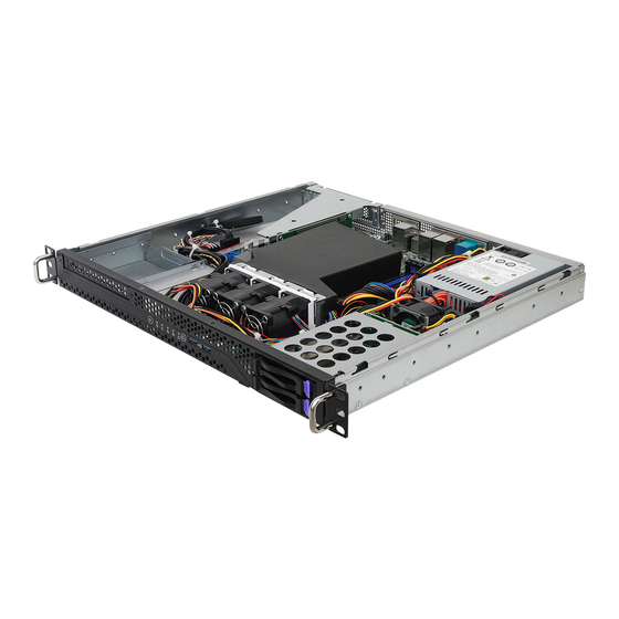
Chapter 2 Server System Overview This chapter provides diagrams showing the location of important components of the server system. 2.1 System Components 1 x Power Supply Unit 4 x Hot-Swap System Fans Server Board 2 x 2.5” SATA HDD Brackets Riser Card Mounting Bracket Front Controls and Indicators 3.5"... -
Page 11: Internal Features
1U2S-B650 2.2 Internal Features From 1 x Riser Card Mounting Bracket (RB1UX16_G4 riser card installed) Serverboard 1 x Power Supply Unit (PSU) System Fan 1 (FAN1) System Fan 4 (FAN4) System Fan 3 (FAN3) System Fan 2 (FAN2) 3.5" SATA HDD (HDD2) or Slim ODD (optional) Front Panel Board (FPB) 2 x 2.5"... -
Page 12: System Front Panel
2.3 System Front Panel HDD0 HDD1 Description 1 x Slim Optical Disk Drive (ODD) (optional) Control Panel Buttons and LEDs 2 x USB 3.2 Gen1 Ports 2 x 2.5" SATA HDD Trays 2.4 System Rear Panel Description 1 x Power Supply Unit I/O Shield (depends on the specification of the server board) Rear Vent 1 x Riser Card Mounting Bracket... -
Page 13: Front Control Panel Buttons And Leds
1U2S-B650 2.5 Front Control Panel Buttons and LEDs Front Control Panel Description Power Button Power Status LED HDD Status LED LAN1 Activity LED LAN2 Activity LED System Status LED System Reset Button USB 3.2 Gen1 Port (USB_1) USB 3.2 Gen1 Port (USB_2) *Please be noted that the functions are supported depending on the type of the server board. - Page 14 Status LED Definitions The control panel located on the front of the chassis has five LEDs. These LEDs provide user with critical information related to different parts of the system. Power LED Status Description Blue Power on Power off HDD Status LED Status Description Blinking Yellow...
-
Page 15: Drive Tray Leds
LED (in order from top to bottom). Description HDD ACT LED HDD STATUS LED Status LED Definitions HDD ACT LED Status Description Solid Green HDD active Blinking Green HDD accessing or reading No HDD HDD STATUS LED Status Description Normal HDD failed (1U2S-B650 not supported) -
Page 16: Chapter 3 Hardware Installation And Maintenance
Chapter 3 Hardware Installation and Maintenance This chapter helps user to assemble the chassis and install components. Before You Begin Before working with the server, pay close attention to the “Important Safety Instructions” at the beginning of this manual. 1. Make sure the server is powered off. Power down the server if it is still running. -
Page 17: Server Top Cover
1U2S-B650 3.1 Server Top Cover Removing the Server Top Cover 1. Before removing the top cover, power off the server and unplug the power cord. 2. The system must be operated with the chassis top cover installed to ensure proper cooling. - Page 18 Installing the Server Top Cover 1. Lower the top cover on the chassis, making sure the side latches align with the cutouts. 2. Slide the top cover toward the front. 3. Secure the top cover with the screws.
-
Page 19: Hard Drive
1U2S-B650 3.2 3.5” Hard Drive Removing a 3.5” Hard Drive Carrier from the Chassis 1. Release the screws that secure the hard drive carrier to the chassis. 2. Lift up and remove the carrier. - Page 20 Installing a 3.5” Hard Drive to the Hard Drive Carrier 1. Place the 3.5" HDD into the carrier with the printed circuit board side facing down. Carefully align the mounting holes in the hard drive and the carrier. 2. Secure the hard drive using the screws. 3.
-
Page 21: Hard Drive
1U2S-B650 3.3 2.5” Hard Drive The system supports 2.5" hard drives. Two 2.5" hard drive trays are located on the front of the system. Removing 2.5” Hard Drive Trays from the Chassis 1. Press the locking lever latch on the drive tray to unlock the retention lever. - Page 22 Installing a 2.5” Hard Drive to the Hard Drive Tray 1. Place a 2.5" HDD into the bracket with the printed circuit board side facing down. 2. Slide the drive tray into the HDD bay until the drive is fully seated. 3.
-
Page 23: System Fan
1U2S-B650 3.4 System Fan System fans are required for the cooling in the system. Please make sure that the chassis top cover is properly installed in order for the cooling air to circulate properly through the chassis and cool the system and components. -
Page 24: Power Supply
3.5 Power Supply This system has a single 315 watt power supply and can accommodate one AC power supply in the bay at the rear of the chassis. If the power supply unit fails, the system will shut down and you will need to replace the power supply unit. -
Page 25: Slim Optical Drive (Optional)
1U2S-B650 3.6 Slim Optical Drive (optional) Removing the Optical Drive Carrier and the Blanking Plate from the Chassis 1. Release the screws that secure the optical drive carrier to the chassis. 2. Lift up and remove the carrier. - Page 26 3. Release the screws that secure the dust filter blanking plate to the chassis. 4. Push to remove the blanking plate and keep it for reassembly.
- Page 27 1U2S-B650 Installing an Optical Drive to the Chassis To use a slim optical drive, you need to purchase a rear SATA/Power adapter seperately. Before installation, secure the rear adapter to the bare drive with screws. Place the slim optical drive into the carrier with the connector end toward the rear side of the carrier where the mounting holes are located.
- Page 28 Place the optical drive assembly back to the chassis with screw holes aligned. Secure the ptical drive assembly to the chassis with two screws.
-
Page 29: Installing The Cpu (Lga 1718 Socket)
1U2S-B650 Appendix A Installing the CPU (LGA 1718 Socket) 1. Before inserting the 1718-Pin CPU into the socket, please check if the PnP cap is on the socket, if the CPU surface is unclean, or if there are any bent pins in the socket. Do not force to insert the CPU into the socket if above situation is found. - Page 30 Carefully place the CPU in as flat as possible. Do not drop it.
- Page 31 1U2S-B650 Make sure the CPU is aligned with the socket before locking it into place. Make sure the black cover plate is always in place until it pops off when closing the socket lever. Please save the cover if the processor is removed. The cover must be placed if wishing to...
-
Page 32: Installing The Cpu Fan And Heatsink
Installing the CPU Fan and Heatsink After installing the CPU into this motherboard, it is necessary to install a larger heatsink and cooling fan to dissipate heat. It also needs to spray thermal grease between the CPU and the heatsink to improve heat dissipation. Make sure that the CPU and the heatsink are securely fastened and in good contact with each other. - Page 33 1U2S-B650...
-
Page 34: Installing The Memory Modules (Dimm)
Appendix B Installing the Memory Modules (DIMM) The DIMM only fits in one correct orientation. It will cause permanent damage to the motherboard and the DIMM if you force the DIMM into the slot at incorrect orientation. For more information about DIMM installation, please refer to the User Manual that comes with the serverboard you use. - Page 35 1U2S-B650 Appendix C Block Diagram...
Need help?
Do you have a question about the 1U2S-B650 and is the answer not in the manual?
Questions and answers