Table of Contents
Advertisement
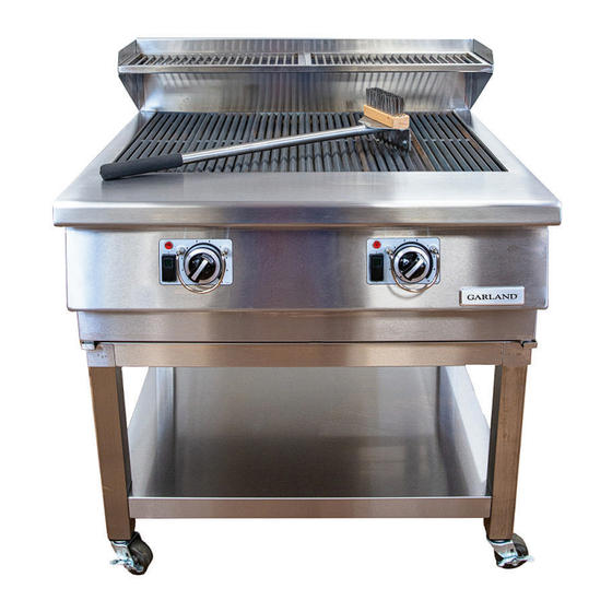
XHP Broiler™
Installation, Operation and Maintenance Manual
Please read all sections of this manual and retain for future reference.
Model: GTXHP36, GTXHP48 & GTXHP60
Warning
Post in a prominent location, instructions to be followed
in the event the user smell gas. This information shall be
obtained by consulting your local gas supplier.
Warning
Improper installation, adjustment, alteration, service
or maintenance can cause property damage, injury, or
death. Read the installation, operating and maintenance
instructions thoroughly before installing or servicing
this equipment.
C
US
Original Instructions
Document #: GAR_IOM_4605246 - Rev4 – 12/23
Bring Your Passion to the Surface
Read these instructions before operating this equipment
and retain for future reference.
FOR YOUR SAFETY
Do not store or use gasoline or other flammable vapors
and liquids in the vicinity of this or any other appliance.
GTXHP36 SHOWN
Caution
Advertisement
Table of Contents

Related Manuals for Garland XHP Broiler GTXHP48


Summary of Contents for Garland XHP Broiler GTXHP48
- Page 1 Bring Your Passion to the Surface XHP Broiler™ Installation, Operation and Maintenance Manual Please read all sections of this manual and retain for future reference. Model: GTXHP36, GTXHP48 & GTXHP60 Warning Caution Post in a prominent location, instructions to be followed Read these instructions before operating this equipment in the event the user smell gas.
- Page 2 THIS PAGE INTENTIONALLY LEFT BLANK Document #: GAR_IOM_4605246 - Rev4 – 12/23...
-
Page 3: Definitions
All utility connections and fixtures must be maintained DEFINITIONS in accordance with local and national codes. As you work on Garland equipment, be sure to pay close attention to the safety notices in this manual. Disregarding DANGER the notices may lead to serious injury and/or damage to the equipment. -
Page 4: Location
Warning Notice This appliance is not intended for use by persons Install the unit in close proximity to a grounded power (including children) with reduced physical, sensory or outlet. Maximum allowable cord length for counter mental capabilities, or lack of experience and knowledge, appliances is 6 ft. -
Page 5: Code
Warning Warning Do not use electrical appliances or accessories other For an appliance equipped with casters, (1) the installation than those supplied by the manufacturer. shall be made with a connector that complies with the Standard for Connectors for Movable Gas Appliances ANSI Z21.69 •... -
Page 6: Cleaning
Caution Caution Do not position the air intake vent near steam or heat Never use an acid based cleaning solution on exterior exhaust of another appliance. panels! Many food products have an acidic content, which can deteriorate the finish. Be sure to clean the stainless steel surfaces. - Page 7 Warning Use caution when handling all metal surface edges of the equipment, use appropriate safety glove if necessary. Warning This equipment is intended for indoor use only. Do not install or operate this equipment in outdoor areas. Warning All covers and access panels must be in place and properly secured, before operating this equipment.
-
Page 8: Table Of Contents
Table of Contents Safety Notices Definitions..............................3 Disclaimers ..............................3 Location ..............................4 Electrical ..............................4 Code ................................5 Clearance ..............................5 Cleaning ..............................6 Personal Protection ..........................6 Section 1 General Information Read This Manual ......................10 Unit Inspection .........................10 Purchaser’s Responsibility ....................10 Additional Requirements ....................10 Items included with the purchase of your new grill from manufacturer .....11 Items NOT INCLUDED from the manufacturer ...............11 Serial Plate Numbers ......................11 Marketing: Model Number Key Description ..............11... - Page 9 Table of Contents (continued) Section 3 Operation Before Turning on the Grill ....................25 Turning on the Grill ......................25 Shutting off the Grill ......................25 Operation of the Grill .......................26 Section 4 Maintenance Maintenance ........................27 Cleaning the Flame Sense/Igniter Probe ................27 Cleaning Under Grates .....................27 Cleaning During Operation .....................28 Cleaning The Stainless Steel Panels ................28 Daily Cleaning Summary ....................29...
-
Page 10: General Information
4. Arrange for an Authorized Sevice Technician to inspect and confirm correct operation of the unit. Do not Garland has developed this manual as a reference guide attempt to operate the grill until connection of utility for the owner/operator and installer of this equipment. -
Page 11: Items Included With The Purchase Of Your New Grill From Manufacturer
Model Number Ke Example: GTXHP36 X = EXTRA P = PERFORMANCE G T X H P 36 G = GARLAND H = HIGH T = TABLETOP 2-DIGIT NUMBER = WIDTH IN INCHES Document #: GAR_IOM_4605246 - Rev4 – 12/23... -
Page 12: Shipping Damage Claim Procedure
Shipping Damage Claim Procedure Please note that Garland equipment is carefully inspected and packed by skilled personnel before leaving the factory. The transportation company assumes full responsibility for safe delivery upon acceptance of the equipment. What to do if the equipment arrives damaged: 1. -
Page 13: Overall Dimension
Section 1 General Information Overall Dimension Model: GTXHP36 Technical Specification GTXHP36 Width Depth Height Packaged Dimensions 41.000" 41.000” 30.250" Overall Dimensions 34.500" 32.532" 20.647” Cook Surface Area 30.719" 21.688" Cook Rack Area 30.688” 7.875” Document #: GAR_IOM_4605246 - Rev4 – 12/23... -
Page 14: Model: Gtxhp48
General Information Section 1 Overall Dimension Model: GTXHP48 Technical Specification GTXHP48 Width Depth Height Packaged Dimensions 54.750" 40.000” 30.000" Overall Dimensions 47.162" 32.532" 20.647” Cook Surface Area 43.381" 21.688" Cook Rack Area 43.475” 7.875” Document #: GAR_IOM_4605246 - Rev4 – 12/23... -
Page 15: Model: Gtxhp60
Section 1 General Information Overall Dimension Model: GTXHP60 Technical Specification GTXHP60 Width Depth Height Packaged Dimensions 63.500" 39.500” 29.000" Overall Dimensions 59.825" 32.532" 20.647” Cook Surface Area 56.044" 21.688" Cook Rack Area 56.626” 7.875” Document #: GAR_IOM_4605246 - Rev4 – 12/23... -
Page 16: Technical Information
General Information Section 1 Technical Information Gas Specification "Input/ Supply Working Model "Total Input Injector Gas Type Burner Pressure Pressure Number of Burners (BTU/h)" Size Connection (BTU/h)" ("W.C) ("W.C.) 3/4" MALE Natural Gas 27,000 54,000 3/4" MALE GTXHP36 Propane 27,000 54,000 11.0 10.0... -
Page 17: High Altitude
Section 1 General Information High Altitude High Altitude – Performance Information Above 2,000 ft, the burner input naturally decreases due to reduced atmospheric pressure. The table below summarizes the performance of the unit for the elevation ranges indicated. INPUT PER BURNER BY GAS TYPE AND INSTALLATION ELEVATION ELEVATION RANGE NATURAL GAS PROPANE... -
Page 18: Clearance To Combustibles
General Information Section 1 Clearance to Combustibles • For indoor installation only • For use in non-combustible locations only • Install under Exhaust hood (see “Exhaust Hood Requirements” in Installation Section) Controls • Power Switch for each burner to control on/off status individually •... -
Page 19: Installation
Section 2 Installation Removing Grill From Wood Crate 2. Remove the cardboard carton and recycle or the top part of the wood skid for larger unit. Important! Upon delivery of your appliance, carefully remove all the protective plastic and keep any documentation. -
Page 20: Location
Installation Section 2 Location Leveling The location selected for the equipment must meet the Position the unit under the hood and in its normal following criteria. If any of this criteria is not met, select operational position. another location. • Level the grill front to back and side to side by adjusting •... -
Page 21: Positioning
Section 2 Installation Positioning Remove the entire top of the unit by removing the hex bolt, then sliding the lock rods forward to release the catch at the Note: Process will be the same for all models. back. Lift straight up to remove the top assembly from the The unit is very heavy and mechanical assistance may be unit. -
Page 22: Splatter Guard Assembly (Optional)
Installation Section 2 Splatter Guard Assembly (Optional) Note: Splatter Guard is optional for all models. Splatter Guard is not included with the purchase of your new broiler from manufacturer. 1. GTXHP36” shown without Splatter Guard 5. Fasten the Right Panel to the Back Panel as shown. The fasteners are provided in the kit. -
Page 23: Remove Stainless Steel Plastic Film
Please contact your edition of National Wiring Regulations (ANSI/NFPA 70 or Garland representative if the unit will be stored in these CSA 22.1/22.2). conditions. -
Page 24: Gas Connection
Installation Section 2 Gas Connection • If there is a momentary power failure (ie: power turns off but comes right back on) when you are operating the • Check the rating plate to determine the type of gas to appliance, the internal gas valves will stop the flow of connect to the unit. -
Page 25: Operation
Section 3 Operation between 500-550°F and the high setting will hold a Important temperature of 700-750°F. It will take approximately The cook grates on this unit have been coated with 30-45 minutes for the unit to heat up and be ready to an organic FDA approved, food safe anti-rust oil at the cook on. -
Page 26: Operation Of The Grill
Operation Section 3 Operation of the Grill Caution • The temperature of the cook surface can be controlled When cooking on the grill, care should be taken not to by adjusting the control knob. Each section of the grill touch hot surfaces. Stainless steel panels close to the can be adjusted and/or turned on or off individually. -
Page 27: Maintenance
Section 4 Maintenance Maintenance • During normal operation and cooking with this unit, the flame sense probe can become contaminated with salts, fats and oils; therefore we recommend cleaning it daily DANGER as follows: To prevent risk of electrical shock, disconnect power Cleaning Under Grates cord before attempting to clean any part of the unit. -
Page 28: Cleaning During Operation
Maintenance Section 4 • Vacuum the large ceramic bricks to remove all loose • Once the unit has cooled, external stainless steel panels debris. A damp cloth or non-metallic scour pad can be should be cleaned using a mild detergent and/or a used to clean any fats/oils that are stuck to the ceramics. -
Page 29: Daily Cleaning Summary
Section 4 Maintenance Daily Cleaning Summary Notice Never clean the inside of the grill with cleaning chemicals or excessive amounts of water. Never remove the base stone. Combination brush and scraper tool. 1. Let the grill cool down for at least 20 minutes before cleaning. - Page 30 Maintenance Section 4 8. Wipe the white ceramic and metal portion of the flame sense probe with a “DRY” cloth. 6. Use a piece of abrasive strip to remove the salts and 9. Clean any fats/oils stuck on the ceramics with a damp oils from the metal cloth or non-metallic scour pad.
-
Page 31: Troubleshooting
The intention of the following troubleshooting Interior testing must be performed by a qualified service diagnostic process is to aid in resolving basic problems. technician only. Do not remove any panel during basic If the problem persists contact a Garland authorized troubleshooting. service technician. Problem... -
Page 32: Wiring Diagram Gtxhp36 (With Center High Limit, No Relays) - Up To Serial# 23121001Xxxxx
Troubleshooting Section 5 Wiring Diagram GTXHP36 (with center high limit, no relays) - Up to Serial# 23121001XXXXX Document #: GAR_IOM_4605246 - Rev4 – 12/23... -
Page 33: Wiring Diagram Gtxhp36 (Without Center High Limit, With Relays) - From Serial# 24011001Xxxxx
Section 5 Troubleshooting Wiring Diagram GTXHP36 (without center high limit, with relays) - From Serial# 24011001XXXXX Document #: GAR_IOM_4605246 - Rev4 – 12/23... -
Page 34: Wiring Diagram Gthxp48
Troubleshooting Section 5 Wiring Diagram GTHXP48 Document #: GAR_IOM_4605246 - Rev4 – 12/23... -
Page 35: Wiring Diagram Gtxhp60
Section 5 Troubleshooting Wiring Diagram GTXHP60 Document #: GAR_IOM_4605246 - Rev4 – 12/23... - Page 36 GARLAND 1177 KAMATO ROAD, MISSISSAUGA, ONTARIO, CANADA, L4W1X4 888-442-7526 WWW.GARLAND-GROUP.COM All rights reserved. Continuing product improvement may necessitate a change of specifications without notice.
Need help?
Do you have a question about the XHP Broiler GTXHP48 and is the answer not in the manual?
Questions and answers