Table of Contents
Advertisement
Quick Links
Advertisement
Table of Contents

Related Manuals for Baker Hughes Waygate Technologies CL 5


Summary of Contents for Baker Hughes Waygate Technologies CL 5
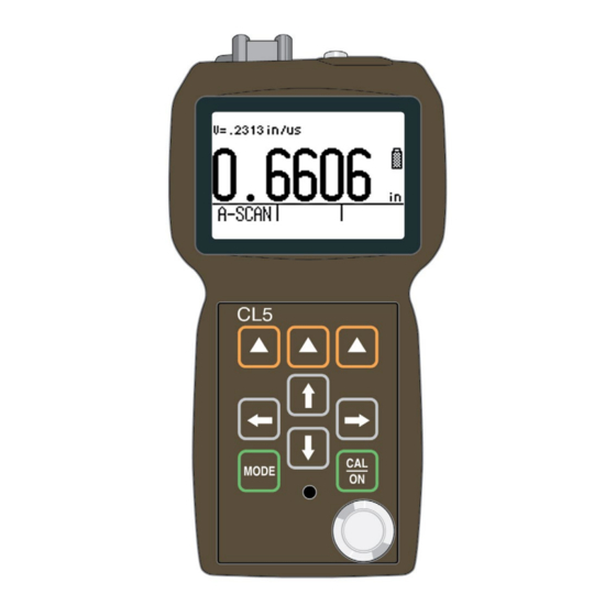
- Page 1 Krautkrämer CL 5 Operating Manual 021-002-296 rev. 04...
-
Page 2: General Information
General Information CL 5... - Page 3 General Information Supplying Power to the CL 5 Supplying Power to the The CL 5 is an ultrasonic precision thickness measurement device. It’s available with optional CL 5 live A-Scan display, acoustic velocity measurement capability, and a data recorder in which as many •...
- Page 4 General Information Supplying Power to the CL 5 FIGURE 1-1—Insert batteries as shown here. Notice the location of the External Power Connector to which the instrument’s Li battery pack’s charger be connected. Issue 04, 08/07 CL 5...
- Page 5 General Information Powering On and Off the Instrument Note: After a power source has been provided, power on the instrument by pressing and holding until the When the battery indicator is in the last quarter instrument turns on. Press and hold when the as indicated by the display-screen symbol instrument is on to turn if off.
- Page 6 General Information Key Features of the CL 5 CL 5 Precision Thickness Measurement • User-selectable measurement resolution to 0.0001 inch (0.001 mm) Base Instrument • Normal (thickness), Min-Scan, Max-Scan, and Contents of the CL 5 Base Instrument Differential/Rate of Reduction Measurement Modes are Standard •...
-
Page 7: What's In This Manual
General Information What’s in this Manual Instrument Options • Overview of instrument features • Explanation of the operating manual contents • A-Scan Upgrade Option Chapter 2—Understanding the Keypad, Menu • Data Recorder Upgrade Option System, and Displays • Velocity Measurement Option •... - Page 8 General Information What’s in this Manual • Adjust the instrument gain setting • Freeze the thickness reading and A-Scan • Specify the nominal material thickness • Connect the digital caliper and measure acoustic velocity (Optional) • Calibrate and zero the instrument/probe combina- tion •...
- Page 9 General Information What‘s in this Manual Chapter 7—Specifications Chapter 8—Maintenance Chapter 9—Appendix • Reset the operating software • Upgrade the operating software • EMC documentation • How to obtain service Chapter 10—Index CL 5...
-
Page 10: Understanding The Keypad
Understanding the Keypad, Menu System, and Displays CL 5 2-10... -
Page 11: Keypad Features
Understanding the Keypad, Menu System, and Displays Keypad Features Keypad Features The CL 5’s display, keypad, and functional commands are easy to interpret and use. In this chapter you’ll find a brief explanation of all display and keypad fea- The instrument’s keypad includes dedicated keys tures. - Page 12 Understanding the Keypad, Menu System, and Displays Interpreting Display Screens FIGURE 2-1—Key Functions 2-12 CL 5...
- Page 13 Understanding the Keypad, Menu System, and Displays Interpreting Display Screens FIGURE 2-2—MEASUREMENT DISPLAY MODE – The display’s appearance varies based on installed instrument options as well as instrument display settings. NORMAL view mode is available in all instruments regardless of the installed options. Additional measurement view modes are available when the A-Scan or Data Recorder options are installed.
- Page 14 Understanding the Keypad, Menu System, and Displays Interpreting Display Screens • Probe Setup Display Mode – • Configuration Display Mode – Allows the user Instrument to select a standard preloaded instrument setup controls are accessed through this screen. The (each matched to a specific probe model) or a controls listed on the configuration display screen custom user-defined setup.
- Page 15 Understanding the Keypad, Menu System, and Displays Interpreting Display Screens FIGURE 2-3—PROBE SETUP DISPLAY MODE – Allows selection of a preloaded or Custom Setup file, which automatically recalls all parameter settings. Note that Custom Setups can be downloaded from an UltraMate©...
- Page 16 Understanding the Keypad, Menu System, and Displays Interpreting Display Screens FIGURE 2-4—FILE DISPLAY MODE – When installed and activated, the data recorder option allows users to create data recorder files, store thickness readings (and accompanying A-Scans), and navigate through file contents as shown here. See Chapter 5 to work with Data Recorder files. 2-16 CL 5...
- Page 17 Understanding the Keypad, Menu System, and Displays Interpreting Display Screens FIGURE 2-5—CONFIGURATION DISPLAY MODE – The contents of the Configuration display depend on the instrument’s installed-option configuration. All settings listed on the Configuration display are described in Section 2.3. CL 5 2-17...
-
Page 18: Working With The Configuration Display
Understanding the Keypad, Menu System, and Displays Working with the Configuration Display Module 2.3 Working with the NOMINAL THICKNESS – Set the nominal thickness value that is then used to calculate and the differen- Configuration Display tial and rate of reduction measurement values when selected by the VIEW MODE parameter. - Page 19 Understanding the Keypad, Menu System, and Displays Working with the Configuration Display Module RADIX BATTERY TYPE – Selects a period (.) or comma (,) to be used – Select the installed battery type to as a decimal point (Section 3.2) ensure accurate remaining battery-life indication.
- Page 20 Setting Up the CL 5 CL 5 3-20...
- Page 21 Setting Up the CL 5 Connecting a Probe and Loading a Setup File Prior to measuring thickness, the instrument must • Set the instrument‘s Gain and Update Rate be properly setup. This chapter explains the steps (Section 3.2) that must be taken prior to measurement, to ensure •...
-
Page 22: Connecting A Probe And Loading A Setup File
Setting Up the CL 5 Connecting a Probe and Loading a Setup File Connecting a Probe and Loading a Setup File Once a probe is connected, press to activate the Prior to measuring thickness, you must connect a Probe Setup display. The Probe Setup display, which is probe to the instrument and select a setup file that’s compatible with the probe (Figure 3-1). - Page 23 Setting Up the CL 5 Configuring the Instrument‘s Display The following instrument settings are automatically adjusted when the Setup file is activated: View Mode Gain Measured Value display resolution Minimum Alarm Setting Maximum Alarm Setting Zero Offset – for contact probes only Velocity Nominal Thickness ...
- Page 24 Setting Up the CL 5 Configuring the Instrument‘s Display FIGURE 3-2—Selecting a Setup File 3-24 CL 5...
-
Page 25: Configuring The Instrument
Setting Up the CL 5 Configuring the Instrument‘s Display 3.2 Configuring the Instrument • Auto Power Down – Select ON to automatically turn the instrument off five minutes after the last key press (no data will be lost) or OFF to allow the in- Prior to using the CL 5 to measure thickness, some strument to remain on until manually powered off. - Page 26 Setting Up the CL 5 Configuring the Instrument‘s Display FIGURE 3-3—Changing Parameter Settings 3-26 CL 5...
- Page 27 Setting Up the CL 5 Instrument Calibration Step 6: Continue selecting other parameters for Step 1: Press modification as outlined in Steps 2 through 5. When Step 2: Select the UPDATE RATE control. complete with all modifications, press to return to the measurement display.
-
Page 28: Instrument Calibration
Setting Up the CL 5 Instrument Calibration Step 3: Press to activate the control, then Calibration requires the use of one or more standards to adjust the selected place value and of known thickness. When a contact probe is installed, select another v alue. - Page 29 Setting Up the CL 5 Setting the Maximum and Minimum Thickness Alarms FIGURE 3-4—Instrument Calibration Procedure CL 5 3-29...
- Page 30 Setting Up the CL 5 Creating and Erasing Custom Setup Files 3.5 Creating and Erasing alarm is violated. Note that the inputted alarm value will correspond to a thickness except when the VELO- Custom Setup Files CITY measurement option is installed and activated. In this case the alarm settings will represent velocity After loading a Standard Setup and performing the values.
- Page 31 Setting Up the CL 5 Locking and Unlocking Instrument Controls FIGURE 3-5—Follow this procedure to create or erase a Custom Setup file. Custom Setup file names may contain up to 16 characters. CL 5 3-31...
- Page 32 Setting Up the CL 5 Locking and Unlocking Instrument Controls Custom Setups created using instruments equip- stored in the file. Note that thickness measurements ped with an optional A-Scan display store the same are part of Data Recorder files (see Chapter 5) and parameters as a base-model unit as well as settings are not stored in Setup files.
- Page 33 Setting Up the CL 5 Locking and Unlocking Instrument Controls 3.6 Locking and Unlocking Instrument Controls Any instrument function can be made nonoperational (locked) using the lockout display. Note that this display is only accessible from the measurement screen. Follow the instructions in Figure 3-6 to access this display and lockout (or enable) some or all function keys.
- Page 34 Setting Up the CL 5 Locking and Unlocking Instrument Controls FIGURE 3-6—Procedure for locking and unlocking function keys 3-34 CL 5...
- Page 35 Setting Up the CL 5 Locking and Unlocking Instrument Controls THIS PAGE LEFT INTENTIONALLY BLANK. CL 5 3-35...
-
Page 36: Measuring Thickness
Measuring Thickness CL 5 4-36... - Page 37 Measuring Thickness Selecting the Displayed View Note: After setting up the instrument, as described in Chapter 3, additional adjustments can be made to Load a Setup file corresponding to the connected select the type of measurement made and the way probe prior to making the adjustments described in in which it is displayed.
- Page 38 Measuring Thickness Selecting the Displayed View Step 2: Press to select the VIEW MODE two). The display also includes a time-out bar, which parameter begins to fill as soon as the probe is uncoupled. Re- coupling the probe before the time-out period expires Step 3: Press to activate this parameter allows the user to continue with the same evaluation...
- Page 39 Measuring Thickness Normal Measurement Mode maximum thickness observed during the evaluation portion of the display and the thickness value period is displayed. Its corresponding A-Scan can is shown in the display’s upper right-hand corner also be displayed by pressing . At this point the (Section 4.5).
- Page 40 Measuring Thickness Normal Measurement Mode 4.2 Normal Measurement Mode When NORMAL view mode is active, the display only contains a thickness reading. While no live A-Scan is (No Live A-Scan) available, an A-Scan Snapshot can be accessed at any time by pressing directly below A-SCAN on the function bar (Figure 4-1).
- Page 41 Measuring Thickness Min Scan and Max Scan Measurement Modes 4.3 Min Scan and Max Scan is complete, display the extreme (minimum or maximum) material thickness observed. During the Measurement Modes evaluation period, thickness is displayed along with the minimum and maximum observed thickness These modes allow the user to continuously evaluate values (Figure 4-2).
- Page 42 Measuring Thickness Quality View Mode 4.4 Quality View Mode When coupled to a part, the thickness value is dis- played. The measurement bar graphic shows where the thickness value is in the range, in relation to the This view mode displays the current measurement lower and upper specified limits.
- Page 43 Measuring Thickness Quality View Mode The arrow below INFO mode toggles the top line of the Quality View mode display to show the File Name or the Test Location Point Name. Quality View Mode requires our optional data recorder option and a custom linear file to work. This Custom Linear File can be created using the Microsoft®...
- Page 44 Measuring Thickness Differential / Rate-of-Reduction Measurement Mode 4.5 Differential / Rate-of-Reduction difference between those two values (measured minus nominal) expressed in percentages and Measurement Mode dimensional terms. Note that the displayed differ- ences can have positive or negative values (Figure This view mode displays the currently measured and 4-3) See Section 4.1 to select view mode and 3.2.3 user-inputted nominal thickness, along with the...
- Page 45 Measuring Thickness Thickness + A-Scan Measurement Mode 4.6 Thickness + A-Scan Measurement Mode (Optional) This optional view mode displays both a live A-Scan display while FREEZE captures the live A-Scan. After reading and corresponding thickness value. Selecting the display is frozen, select ZOOM to magnify the trig- FIND moves the triggering echo to the center of the gering echo (Figure 4-4) FIGURE 4-4—TK + A-Scan view mode diplays, freezes, and magnifies a live A-Scan...
- Page 46 Velocity Measurement Mode Velocity Measurement Mode (Optional) This optional view mode displays measured material 3.2.3) or by using the digital micrometer supplied with velocity (see Section 4.1 to select mode). The mate- all instruments that incorporate the Velocity option. rial velocity calculation depends on the value inputted (Figures 4-5 and 4-6).
- Page 47 Measuring Thickness Velocity Measurement Mode FIGURE 4-6—Direct input of nominal thickness in VELOCITY mode. CL 5 4-47...
- Page 48 Typical Sound Velocities in Various Materials Rubber (Butyl) 1900 (Longitudinal Wave) Inconel 2200 5600 Rubber (Vulc.) 2300 in/s x 10 Lead 2200 Silver 1400 3600 Magnesium 2300 5800 Aluminum 2500 6300 Steel 2300 5800 Nylon 1000 2500 Manganese 1800 4600 Brass 1700 4300...
-
Page 49: Using The Optional Data Recorder
Using the Optional Data Recorder CL 5 5-49... -
Page 50: Creating A New Data Recorder File
Using the Optional Data Recorder Creating a New Data Recorder File Creating a New Data Note: Recorder File The instructions here apply only to instruments equipped with a Data Recorder including a SD card. To create a new Data Recorder file, you need to When installed and activated, the data recorder specify a file name and top and bottom position. - Page 51 Using the Optional Data Recorder Creating a New Data Recorder File FIGURE 5-1—Creating a New Data Recorder File CL 5 5-51...
-
Page 52: Recalling And Erasing Stored Data Recorder Files
Using the Optional Data Recorder Recalling and Erasing Stored Data Recorder Files 5.2 Recalling and Erasing Stored Step 1: Press to access the CONFIGURATION dis- play, then set DATA RECORDER to ON. Data Recorder Files Step 2: Press again to launch the File Display mode Stored files can be recalled or erased at any time. - Page 53 Using the Optional Data Recorder Recording Thickness Measurements in Data Recorder Files 5.3 Recording Thickness and Step 4: Press arrows to select the stored file you wish to recall, and ten press . Velocity Measurements in Data Recorder Files To erase a Data Recorder file: Step 1: Press to launch the File Display mode The Data Recorder must be enabled (turned ON) via Step 2: If required, press arrow below FILES to obtain a...
- Page 54 Using the Optional Data Recorder Printing a Report Note: 5.3.2 Navigating Through Data Recorder Files Pressing below SEND with the instrument connected to a PC that has the applicable software installed and When the Data Recorder is turned on, the contents of running will result in the thickness reading being sent the active Data Recorder file are displayed in the out the I/O port as described in Section 6.1.
-
Page 55: Printing A Report
Using the Optional Data Recorder Printing a Report 5.4 Printing a Report Step 1: Press to access the Data Recorder file display as shown in Figure 5-2. Note: Step 2: Follow the regular procedure to select the file to be printed. The following procedure explains how to print the contents of a stored Data Recorder file. - Page 56 Using the Optional Data Recorder Printing a Report THIS PAGE LEFT INTENTIONALLY BLANK. 5-56 CL 5...
- Page 57 I/O Features CL 5 6-57...
- Page 58 I/O Features Transmitting Thickness Data Through an External Device Note: In this chapter you will find: • The byte structure used when thickness readings The instructions in this chapter apply to all are transmitted through the I/O port (Section 6.1) instruments.
- Page 59 I/O Features Transmitting Thickness Data Through an External Device CL 5 6-59...
-
Page 60: Remote Commands
I/O Features Setting Communication Speed and Type 6.2 Setting Communication instrument settings can be done remotely by using a user written program or a commercially available Speed (Baud Rate) and serial communications program such as Windows™ Connecting to a PC HyperTerminal. - Page 61 I/O Features Setting Communication Speed and Type Remote Control Codes: The following is a partial listing of remote commands. Additional remote commands are available upon request. Strings inside [ ] are values / parameters CL 5 6-61...
- Page 62 I/O Features Setting Communication Speed and Type Code Query Parameter Range Resolution Function Yes (not req.) Identification: INSTRUMENT returns “CL5”. Directory of Parameter Sets: INSTRUMENT will return a list of parameter sets (custom setups) in the same format as the file directory structure: Yes (not req.) 0001 XXXXXXXXXXXXXXXX 0002 XXXXXXXXXXXXXXXX...
- Page 63 INSTRUMENT will transmit the file indicated by (n). file num- 1 to (n) should be the file number as displayed on the ber on dir Number directory list. list of files (only supported when Data Recorder option is enabled.) (Continued) CL 5 6-63...
- Page 64 I/O Features Setting Communication Speed and Type Code Query Parameter Range Resolution Function Parameter Set Download: INSTRUMENT will go into 0 to 11 parameter set download mode sending the re- Parameter quested parameter set. [n] indicates the parameter PD [n] (0 to 12 if ve- set number set number that is requested.
- Page 65 Key Press: [n] = value indicated what key press to execute. KCODE_F1 KCODE_F2 KCODE_F3 key press 7K [n] code KCODE_UP_ARROW KCODE_DOWN_ARROW KCODE_LEFT_ARROW KCODE_RIGHT_ARROW KCODE_MODE KCODE_ON_CAL HOME: Sets instrument to TG measurement view mode. (Continued) CL 5 6-65...
- Page 66 I/O Features Setting Communication Speed and Type Code Query Parameter Range Resolution Function Soft parameter reset. Resets the following parameters to their defaults: View Mode: Thickness Radix: PERIOD Backlight: OFF Language: English Batteries: Alkaline (unless Li battery is detected) Power Down: Auto Units: INCH Resolution: X.XXX Lock Outs: OFF (all lockout parameters)
- Page 67 Query for the present instrument thickness, ve- locity, couple status Will dump data containing the bitmap of the LCD display memory in one of several formats. Memory Dump This is the binary dump. This dumps the video memory byte for byte. (Continued) CL 5 6-67...
- Page 68 I/O Features Setting Communication Speed and Type Code Query Parameter Range Resolution Function Query for the present instrument thickness, velocity, couple status: Output Format: (comma delimited fields) Thickness , Velocity , couple status Thickness will always be a whole number in .001 mm resolution.
-
Page 69: Specifications
Specifications CL 5 7-69... -
Page 70: Instrument Specifications
Specifications Instrument Specifications This chapter lists the features and specifications of your CL 5 including: • Instrument Specifications (Section 7.1) • Features of the Optional A-Scan (Section 7.2) • Features of the Velocity Measurement Option (Section 7.3) • Features of the Optional Data Recorder (Section 7.4) •... - Page 71 Specifications Instrument Specifications Units: Inch or millimeter Calibration: Enter velocity or thickness Contact: One point or Two point calibration Delay: One point Pulser: Excitation Pulse: Spike Pulser Voltage: 100 V into 50 ohm load, using 20 MHz Scope Receiver Bandwidth: 1.0 to 16 MHz @ -6 dB Gain: Automatic Gain Control...
- Page 72 Specifications Instrument Specifications Display of Last Reading: Solid filled or hollow digits indicate coupled or uncoupled condition. Setups: 6 Standard Setups for Contact and Delay probes 5 Custom Setups with up to 16 character alphanumeric name Alarm Settings: Minimum and Maximum Alarms Range of 0.005-20 in.
- Page 73 Specifications A-Scan Option Parameter Adjustments I/O Connectors Transducer: 00 Lemo (coax) RS-232, Battery Charger: Micro—D9 (Female), Charger 100–240 V, 50–60 Hz Temperature Operating: +10°F to +140°F (-10°C to +60°C) Storage: -10°F to +160°F (-20°C to +70°C) Weight: 0.92 lbs. (420 g) including batteries Size: 7.1”...
-
Page 74: Data Recorder Option Features
Specifications Data Recorder Option Features 7.4 Data Recorder Option Features Capacity: 120 files each containing 10,000 readings with or without A-Scan attachments (May vary based on size of SD card used.) File Structures Grid created from instrument keypad and Custom Linear created with UltraMATE File Naming: Up to 24 character alphanumeric name... - Page 75 Specifications Cl 5 Probe/Transducer Specifications Model Probe Nominal Contact Measuring Type Freq. Diameter Range Alpha 2F & CLF5 Fingertip Contact 10 MHz 0.38 in. 0.060 to 10.0 in. 9.5 mm 1.52 to 254 mm Steel Alpha DFR-P Plastics, Delay Line 22 MHz 0.30 in.
- Page 76 Specifications CL 5 Probe/Transducer Specifications THIS PAGE WAS INTENTIONALLY LEFT BLANK. 7-76 CL 5...
-
Page 77: Maintenance
Maintenance CL 5 8-77... -
Page 78: Care Of The Instrument
Maintenance Care of the Instrument Care of the Instrument Proper Cable Handling • Avoid twisting or knotting of the cable Clean the instrument housing and display using a soft cloth lightly dampened with water or a mild • Grasp the cable only by the connectors when window-cleaning product. - Page 79 Appendix CL 5 9-79...
-
Page 80: Resetting The Operating Software
Appendix Resetting the Operating Software and hold down . Continue to press both keys for This section contains supplementary information including instructions on: approximately three (3) seconds until the power-on sequence is initiated. • Resetting the Instrument’s Operating Software Step 3: A successful reset is acknowledged when the •... - Page 81 Appendix Upgrading the Operating Software • Up to date information on operating software The program will connect to the Waygate Technolo- gies, FTP site (you may need to be connected to the • Latest upgrade utility program Internet prior to this operation). The program checks the version you have on your machine against the •...
-
Page 82: Manufacturer/Service Addresses
Das CL 5 wird hergestellt von: the product service page accessible from waygate- tech.com to locate your local WAygate Technologies re- Baker Hughes Digital Solutions GmbH presentative, or contact one of the following addresses: Robert-Bosch-Straße 3 Germany 50354 Hürth... - Page 83 France Waygate Technologies Scs 68, Chemin des Ormeaux 69760 Limonest France Telephone +33 4 72 - 17 92 20 +33 4 78 - 47 56 98 Waygate Technologies, LP 201 Beltway Green Pasadena, TX 77503 Telephone +1 832-325-4368 CL 5 9-83...
- Page 84 Index CL 5 10-84...
- Page 85 Index Custom Setups .........3-32 A-Scan Upgrade Option ......1-15 ADVANCE Direction ........ 5-59 Data Recorder file ........5-59 alarm ............3-41 Data Recorder Upgrade Option ....1-17 Auto Power Down ........3-34 Decimal ............ 3-35 Differential / Rate-of-Reduction Measurement Mode ......4-53 Backlight ..........
- Page 86 Index Gain ............3-36 Nominal Thickness ......... 3-36 NORMAL view ...........4-49 NOTES ............5-59 I/O port ............6-67 operating software ......... 9-87 Options ............1-16 Key functions ..........2-21 Keypad ............2-21 POWER DOWN .......... 2-28 Powering On..........1-14 Language ..........3-35 Printing a Report ........5-64 Lithium (Li) battery........
- Page 87 Index Safety ............0-9 Units ............3-35 SEND ............5-63 Update Rate ..........3-36 Serial PC Cable ........6-67 upgrade utility program ....... 9-87 Service ..........0-10, 9-90 SETUP DISPLAY MODE .......2-26 Setup File ........... 3-31 Velocity Measurement Mode ....4-55 Software ...........
- Page 88 Waygate Technologies is an active participant in Europe’s Waste Electrical and Electronic Equipment (WEEE) take-back initiative, directive 2002/96/EC. The equipment you purchased required the extraction and use of natural resources for its production. It may contain hazardous substances that could impact health and the environment. In order to avoid the dissemination of those substances in our environment and to diminish the pressure on the natural resources, we encourage you to use the appropriate take-back systems.
- Page 89 RemoteService@bakerhughes.com waygate-tech.com © 2021 Baker Hughes All rights reserved. Specifications subject to change without notice. bakerhughes.com...
Need help?
Do you have a question about the Waygate Technologies CL 5 and is the answer not in the manual?
Questions and answers