
Related Manuals for Sorel WMC


Summary of Contents for Sorel WMC
- Page 1 Heat Metering Controller WMC Installation and operating instructions Read carefully before installation, commissioning and operation...
-
Page 2: Table Of Contents
Table of content Safety instructions A. - 4.2.2.1. / 4.2.3.1. - RPS Typ A.1. - EC declaration of conformity 4.2.2.2. / 4.2.3.2. - Pmin A.2. - General instructions 4.2.2.3. / 4.2.3.3. - Pmax A.3. - Explanation of symbols A.4. - Changes to the unit 5. -
Page 3: Safety Instructions
Safety instructions A.1. - EC declaration of conformity By affixing the CE mark to the unit the manufacturer declares that the WMC conforms to the following relevant safety regulations: EC low voltage directive 2006/95/EC EC electromagnetic compatibility directive 2004/108/EC Conformity has been verified and the corresponding documentation and the EC declaration of conformity are kept on file by the manufacturer. -
Page 4: Changes To The Unit
Description of controller A.4. - Changes to the unit • Changes, additions to or conversion of the unit are not permiddled without the written permission from the manufacturer • It is likewise forbidden to install additional components that have not been tested together with the unit •... -
Page 5: Description Of Controller
Description of controller B.1. - Specifications Electrical specifications: Mains voltage 100 - 240VAC Mains frequency 50 - 60Hz Power consumption 0,5W - 2,5W Internal fuse T2A / 250V slow blow Protection category IP40 Protection class Overvoltage Category Degree of Pollution Category mechanical relay 460VA for AC1 / 460W for AC3 3 (R1-R3) 0-10V output, tolerance 10%, 10 k Ω... -
Page 6: Temperature Resistance Table For Pt1000 Sensors
For each step in the input process the individual entry keys are assigned to appropriate functions and explained. The controller menu contains headwords for the measured values and settings, as well as help texts or clearly-structured graphics. The WMC can be used as a Heat Metering Controller for the various system variants. -
Page 7: Installation
Installation C.1. - Electrical connection Before working on the unit, switch off the power supply and secure it against being switched on again! Check for the absence of power! Electrical connections may only be made by a specialist and in compliance with the applicable regulations. -
Page 8: Wall Instalion
Installation C.2. - Wall instalion Install the controller only in dry areas and under the ambient conditions described under B.1 “Specifications”. Achtung 1. Unscrew cover screw completely C.2.1. 2. Carefully pull upper part of housing from lower part. 3. Set upper part of housing aside, being sure not to touch the electronics when doing so. - Page 9 Installation Select necessary C.2.3. program/hydraulics Strip cables by 55mmmax., insert, fit the strain relief devices, strip the last 8-9mm of the wires (Fig. „C.2.3.“) Open the terminals using a suitable screwdriver (Fig. „C.2.4.“) and make electrical connections on the controller Refit terminal connection cover and fasten screw.
-
Page 10: Installing The Temperature Sensors
Installation C.3. - Installing the temperature sensors The controller operates with Pt1000 temperature sensors which are accurate to the degree, thus ensuring optimal control of system functions. The temperature sensor cables must be routed separately from mains voltage cables, and must not, for example, be routed in the same cable duct! Caution Sensor cables for S1 and S5 can be extended to a maximum of 30m using a cable with a cross-section of at least 0.75mm². -
Page 11: Terminal Connection
Installation D.1. - Terminal connection diagram mains side 100-240VAC max. 12V Caution Danger CAN CAN VFS2 VFS1 PELV Low voltage max. 12VAC/DC Mains voltage 100-240VAC 50-60Hz Terminal: Connection for: Terminal: Connection for: Temperature sensor 1 Mains phase conductor L Temperature sensor 2 Mains neutral conductor N Temperature sensor 3 Relay 1... -
Page 12: Display And Input
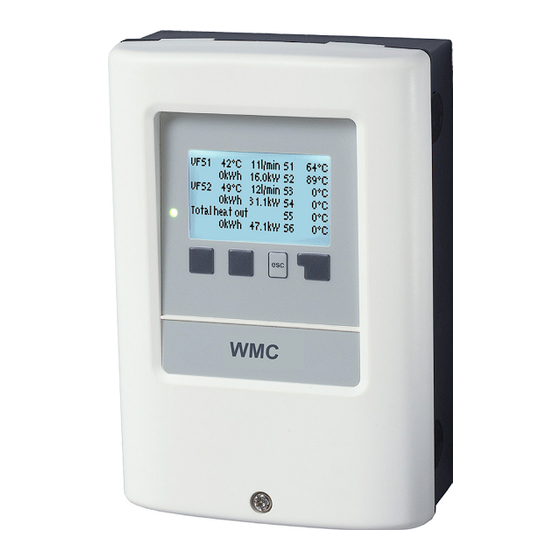
Operation E.1. - Display and input The display (1), with its extensive text and graphics mode, is almost self-explanatory, allowing easy operation of the controller. To change from the overview to the settings menu, press the „esc“ key. The green status LED (2) lights up when a relay is active, the red LED blinks when an error occurs. -
Page 13: Commissioning Help
Operation E.2. - Commissioning help The first time the controller is turned on and after the language and time are set, a query appears as to whether you want to parametrise the controller using the commissioning help or not. The commissioning help can also be terminated or called up again at any time in the special functions menu. -
Page 14: Menu Sequence And Menu Structure
Operation E.4. - Menu sequence and menu structure The graphics or overview mode appears when no key has been press for 2 minutes, or when the main menu is exited by pressing “esc“. The up and down buttons are used to scroll through the list of sensors and relays . -
Page 15: Measurement Values
Measurement values 1. - Measurement values The menu “1. Measurement values” serves to display the currently measured temperatures. The menu is closed by pressing “esc” or selecting “Exit measurement values”. Selecting “Overview” or “esc” exits the Info mode. If “--” appears on the display instead of the measurement value, then there may be a defective or incorrect temperature sensor. -
Page 16: Operating Modes
Operating modes 3. - Operating modes In menu “3. Operating modes” the controller can either be placed in automatic mode, switched off, or placed in a manual operating mode. The menu is closed by pressing “esc” or selecting “Exit operating modes”. 3.1. -
Page 17: Settings
Settings 4. - Settings The necessary basic settings required for the control function are made in menu “4. Settings”. This does not under any circumstances replace the safety facilities to be provided by the customer! Caution The menu is closed by pressing “esc” or selecting “Exit settings”. -
Page 18: Pressure Monitor
Settings 4.2. - Pressure monitor The relay is switched on when the pressure drops below set minimum or exceeds the set maximum pressure. 4.2.1. - Pressure monitor This menu is used to configure the system pressure montoring via direct sensor. As soon as the set limits are exceeded, the relay is switched on. -
Page 19: Special Functions
Special functions 5. - Special functions Menu “5. Special functions” is used to set basic items and expanded functions. Other than the time all settings may only be made by a specialist. Caution The menu is closed by pressing “esc” or selecting “Exit special functions”. -
Page 20: Sensor Calibration
Special functions 5.4. - Sensor calibration Deviations in the temperature values displayed, for example due to cables which are to long or sensors which are not positioned optimally, can be compensated for manually here. The settings can be made for each individual sensor in steps of 0.8°C (temperature) resp. -
Page 21: Menu Lock
Menu lock, Service values, languages 6. - Menu lock Menu “6. Menu lock” can be used to secure the controller against unintentional changing of the set values. The menu is closed by pressing “esc” or selecting “Exit menu lock”. The menus listed below remain completely accessible despite the menu lock being activated, and can be used to make adjustments if necessary: Measurement values Statistics... -
Page 22: Malfunctions With Error Messages
Malfunctions Z.1. Malfunctions with error messages If the controller detects a malfunction, the red light flashes and the warning symbol also appears in the display. If the error is no longer present, the warning symbol changes to an info symbol and the red light no Led blinks + warning symbol) longer flashes. -
Page 23: Replacing The Fuse
Malfunctions Replacing the fuse Repairs and maintenance may only be performed by a specialist. Before working on the unit, switch off the power supply and secure it against being switched on again! Check for the absence of power! Danger Only use the supplied spare fuse or fuses of the same design with the following specifications: T2A / 250V . - Page 24 (see 2.) at regular intervals. Hydraulic variant set: Commissioned on: Commissioned by: Notes: Your specialist dealer: Manufacturer: SOREL GmbH Mikroelektronik Reme Str. 12 D - 58300 Wetter (Ruhr) Tel. +49 (0)23 35 682 77 0 +49 (0)23 35 682 77 10 www.sorel.de info@sorel.de...
Need help?
Do you have a question about the WMC and is the answer not in the manual?
Questions and answers